
Brian’s Boards
Brians design concepts are slightly different as he has explained elsewhere on this site:
Brian says:
Although it can all be done with the Rpi, I still used an arduino on the board because it can then be used to connect to Pi or to a pc running Arena. Would also be easy to upgrade to other single board computers that may become available.
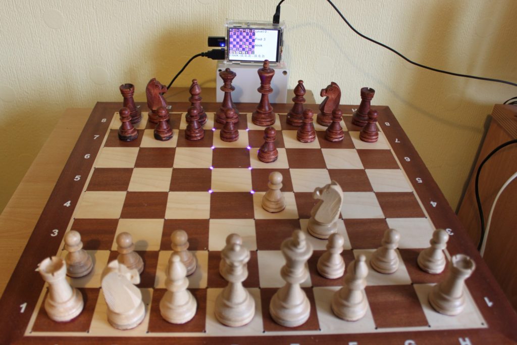
I wanted the leds to light on four corners of the selected square, but you then need a 9*9 led array. I used 2*MAX2719 kits and dumped the led matrix that they were supplied with..
For the board I used a wooden tournament board from ebay (£22).
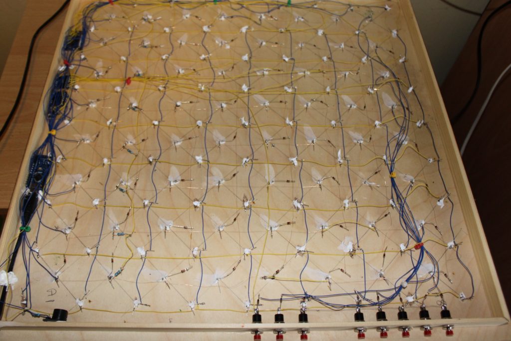
drilled 3mm holes at each square corner for the led’s and another hole from the back of the board in the centre of each square (not all the way through) to mount the reed switches and diodes. To allow space for the electronics and wiring under the board I will add wooden mouldings around the edges.
I want to recommend my method for the board because it is so simple and works so well.
I bought this board on ebay http://www.ebay.co.uk/itm/152207797934
drill a 3mm hole at each corner of every square for the led’s.
counter drill from the back not all the way through because the led base is bigger than the top
drill a 3mm hole again not all the way through to insert the reeds vertically. ( i use a bit of pipe on the drill bit to set the depth.(use needle pliers to bend the reed wires or you will break the reed switch). both ends protrude from the hole.
The reeds will stick out <1cm, also you need to mount the electronics on the back, so add a rim around the board 1-2 cm’s to allow for this.
so no need to hollow out the board and no pcb for the switches/leds required.
Thanks so much for this site. You’ve inspired me to take on a similar project. I like the LED setup for Brian’s board. I’m assuming that those are 3mm LEDs since it said 3mm holes, is this correct? Also, are there any additional details available on the wiring schematic for Brian’s setup? I can’t quite make out how everything is connected via the photograph.
Bryan, You can use any size LED you want. Brian has one LED in each corner, so I guess smaller 3mm look better. I have on 5mm LED at the bottom right of each square. The logic and wiring are the same so its a matter of personal taste.
As for a wiring diagram I reference this diagram for an 8×8 matrix on the Arduino, but its the same for a Raspberry PI. Instead of being driven by an MAX72XX you use an HT16K33 because Adafruit have written easy to use Python libraries. In both cases you just need to make sure you get the Anodes and Cathodes the right way around. See this Adafruit diagram. Its easy to try it out on a 3×3 matrix on a breadboard first.
They are 3mm led’s. but the photo of the front is my first prototype board, the one of the back is my second one with vertical reed relays. The led’s are not wired up yet in that picture.
Note: it needs to be a 9*9 matrix of led’s if you use one in each corner of the squares. the HT16K33 is 16* 8 so a bit of fudging needs to be done, I’ll provide a diagram and photo when it’s done, but for it to work you will need the same software as well as the same wiring. and I am using an arduino, and I will upload my software to github
Hi Brian I just LOVE your design I ‘m in the process of doing the same concept.
Can I have more details please?
Thank you
All the files are on github.
https://github.com/Ernisius/Picochess-nonDGT/tree/master/Picochess-nonDGT
Including the circuit diagrams (chesboard.fzz) in friting format.
The arduino scripts and the modified picochess python scripts.
Let me know if you need any more information.
Thank you Brian.
it is very interesting.
very good job
Hi Brian
It is very difficult to find out what file is for what. – Can you arrange them in appropriate folder/function please?.
On the Fritzing file the upper group (HT16K33) is not connected to the Arduino section. Is it straight forward or no?
is there any photos or video to see how whole project work and how you inserted the reeds on the backside.
Brilliant again thank you for sharing this amazing project.
Warm regards
Sofian
Hi Sofian,
The Arduino files are in the folder Arduino-Chessboard. After building the board you can test it works using the serial monitor from the ardunio sketch
Chessboard.fzz is the wiring for the chessboard.
The only connections from the arduino to HT16K33 are the SDA and SCL .
All the rest of the files are for picochess. this folder structure must be kept intact and copied to the raspberry pi as is. This part can be difficult to get working if you don’t know python, so I would recommend downloading the picochess image from their website and after writing that to a sd card (instructions are on their website). replace the contents of the original picochess folder with my modified files.
I will send photos of my completed build to Max, for him to upload here if possible.
Brian, yes send me any stuff you want uploaded, Max
Sorry i’m not to good with python. And i’m doing this as a school project. Can you please give me a detailed parts list for everything needed, and email me all required files, and explain how to run it. Because I couldn’t find all the required files on this website, and the install instructions weren’t easy to understand. Thanks.
Dooby, sorry don’t have what you need. You will see that Brian has given a Github address for his software, other sites such as the Solus Project describes construction in great detail.With that and Brians software , plus tips on this site you should have all you need, however if you are “Not to good with Python” you may want to build a simpler project first to improve skills.Like the NOX project on this site
Thanks, I now think I understand the hardware part, but which reed switches would you recommend (size, website, and price). Also is all the required software on this website.
Stockfish I have, Chessboard I have. The program that talks to Stockfish I have, but is there a program that controls the LEDS, reed switches, LCD screen and communicates to the Program that controls stockfish?
Thanks.
I’m just starting to build my board, I hooked up a few reed switches to a MCP23017 and my Raspberry Pi. Using your code and working great, thanks very helpful. I was going to do the routed board and lay them flat but they seem to only close when the magnet is at either end with a dead spot in the middle. My board is intentionally a bit smaller so my robot arm doesn’t have to reach so far. Each square is only 3cm so putting them in at angles will be too close to the next square. So I think Brian’s vertical reed option will best fit my needs although I’m slightly concerned about over drilling, I’ll look for some pipe. With a robot arm I don’t need to worry about the LED’s. I have a Nokia 5110 screen to use as a display and a few switches to control it.
You can use the plastic sleeve of a cheap biro for the tube,
Has anyone looked at using hall effect sensors for piece recognition.
You could use north south poles for colour, then either different strength magnets or set the magnets in the chess pieces at different depths for the 6 piece types. Or a combination of both.
These are the cheapest I’ve seen
http://www.ebay.co.uk/itm/50pcs-Hall-element-49E-OH49E-SS49E-linear-Hall-switch-/270871990444?hash=item3f113a90ac:m:mdzYXtEqhwZei9N0Y-HDlSw
How much wire does one need to build the board with the 64 or the one with 81 LED respectively, including all the other ones for the reed switches and so on? I don’t have any wire yet and ask myself what wire and how much of it I need.
I used this,
http://www.ebay.co.uk/itm/261443218575?_trksid=p2060353.m2749.l2649&ssPageName=STRK%3AMEBIDX%3AIT.
Also good for wrapping round header pins on the arduino ( if you have the wire wrap tool)
Hi Brian,
Can you elaborate on how you inserted the reed switches vertically? I cant seem to determine it from your picture.
Many Thanks,
Sam.
Hi Sam,
I just bent one wire all the way around so both wires face up. (use needle pliers or you will break the relay). then push the other end into the 3mm hole. both wires point up and are then accessible. The white blobs are silicon I used to seal the relay into the hole.
Hi Brian,
a couple of years ago I made an attempt to build your board, but had then other things to do – now I will start a new attempt!
Thanks for sharing!
Regards, Michael
I’ve updated it since then. I got rid of the 4″ display because the picochess webserver has more functionality.
I added a 4 line LCD display for configuring level/engine/boo/ time etc.
Also I swapped 2 0f the buttons for shaft encoder. because it’s easier to scroll up and down menus, especially if you have 60 chess engines to choose from.
Here is the github link
https://github.com/Ernisius/Picochess_NonDGT_LCD_0.9j
Brian, Please share your mail id
Hello Sir Brian is there a video for step by step making of this project?
Sorry no. I initially only did this project for myself, so didn’t produce any step by step instructions.
But all the information you need to build this is uploaded to github.
Including circuit diagram in fritzing format, arduino code and picochess code.
Iv’e seen already the new (updated project).
*I don’t see a diagram on how to connect the LCD it is to Rpi or Arduino?
*It is possible to just used a single LED to chess tile?
*It is okay to get your’e email for further information?
Hello again sir brian, im already done with the usb chessboard, connect the
HT16k33 – SDA t0 A4(nano) and HT16k33 – SCL to A5(nano)
I followed the comments in the arduino for the IC (4017 and 4021 ) connection to the arduino and plug the arduino nano directly to the usb port of rpi but mine doesn’t work.
I installed DISKIMAGE picochess v0.9n – Revelation2 Pi Mode on my 8gb sdcard since v.09j is not on the list. I need help thank you.
How to connect the LCD or 4″ to rpi?
regards, Mark
Hi Mark
My project on github is not fully up to date, I am currently working through a few improvements which I will upload in a few weeks, using picochess version n.
The LCD is connected to the pi in the version on github, but I will move it to the arduino in the next update.
This is to make the chessboard stand alone, so it can be used on the pi or a pc running windows or linux.
You can very easily modify the circuit and code to use 1 led per square, it is in fact easier, than with 4 leds, I just prefer it that way.
I recommend to get it working treat the reed matrix and led systems separately.
Use the serial monitor on the arduino sketch to test responses when you put magnets over the reeds. If it doesn’t work, reduce the complexity by writing short bits of code to test specific parts of the circuit. Also have you put power smoothing capacitors (10nf) across the 5v power close to each chip.?
I am also experimenting with using a teensy 2.0++ so as to eliminate the 4021/4017 matrix scanning.
Mark
If you go to google group picochess, there is more discussion on this there, and you will be able to send me a pm.
Thank you so much sir Brian, sorry for the trouble.
I’ve seen the 10nf in the diagrams/actual photo, but dont know where to put them. Btw im doing for school project.
When I open the serial monitor and change the baud rate into 115200, newgame: w appears and Both corners( where the chess pieces located) of the LED flickers I tried to move a single pawn piece but nothing happens on the Serial Monitor.
It is okay to used an Common Cathode LED an alternative to the that you used?
I will try to find you sir in Picochess group.
regards, Mark
Hi Brian!
this link is not lalid now. Here is the github link
https://github.com/Ernisius/Picochess_NonDGT_LCD_0.9j
Do you have an updated link to this or updated version?
Im trying to build a non DGT system and any help is greatly appreciated!
Best regards Hans
This is always a work in progress but here is the new link.
https://github.com/Ernisius/Picochess-NonDGT_PI
or alternative to connect to PC
https://github.com/Ernisius/picochess_nonDGT_PC.
If you go to https://groups.google.com/forum/#!forum/picochess
you can get some help there.
Brian, since you are orienting your reed switches differently than Max (perpendicular to the plane of the chess board instead of parallel) do you need to use different types of magnets in the chess pieces to account for the different orientation?
Use the same magnets. I found mounting them vertically they respond more reliabley because reed switches are activated with the magnet at either end, but not in the middle.
It is more difficult to mount them this way, so it’s up to you if it’s worth the effort.
Hello,
I know this thread is old, but since I haven’t found any explanation (nor photos) in the INET to make a 9×9 led matrix with the HT16K33 board, I decided to share my experiences to finally build a working schematic design.
The photo of chessboard prototype can be downloaded from:
https://drive.google.com/file/d/1y85ndrFoy84Jdc7OPAKt0pTN6cdVWeGf/view?usp=share_link
The first thing to understand is that to overcome the limits of an 8×8 matrix, we must design a 16×8 matrix, but the logic of the HT16K33 board tells us that it handles two 8×8 matrices stuck together. See:
https://learn.adafruit.com/assets/36273
Therefore I have designed all of this as follows:
……Second……..First
……Board……….Board 8×8
…..CATHODES ->
A… -O-O.. Pin C7
N… -O-O.. Pin C6
O… -O-O.. Pin C5
D… -O-O.. Pin C4
E… -O-O.. Pin C3
S… -O-O.. Pin C2
….. -O-O.. Pin C1
…O-O-O.. Pin C0
Anodes are plugged to:
Pin A10-A9-A8-A7-A6-A5-A4-A3-A2-A1-A0 (from left to right)
Now, the trick is to flip the first two columns (the ones furthest to the left); we place them on the top row of our chessboard, keeping the original wiring connections (of course the wire will have to be longer :))
…-O
…-O
…-O
…-O
…-O
…-O
…-O
O-O
happens to be:
O-O-O-O-O-O-O-O — O
we can see in the photo a coarse red wiring, but quite explanatory (from the visual point of view).
Finally, I show some Python code for testing purposes only.
import time
# Import all board pins and bus interface.
import board
import busio
# Import the HT16K33 LED matrix module.
from adafruit_ht16k33 import matrix
# Create the I2C interface.
#i2c = busio.I2C(board.SCL, board.SDA)
i2c = busio.I2C(board.GP1, board.GP0) # Pi Pico RP2040
matrix = matrix.Matrix16x8(i2c)
# Clear the matrix.
matrix.fill(0)
time.sleep(2)
matrix.fill(0)
matrix[8,0] = 1
time.sleep(2)
matrix[9,0] =1
matrix[10,0] =1
time.sleep(2)
matrix.fill(0)
matrix[11,0] =1
matrix[12,0] =1
time.sleep(2)
matrix.fill(0)
matrix[13,0] =1
matrix[14,0] =1
matrix[15,0] =1
time.sleep(2)
matrix.fill(0)
matrix[15,1] =1
time.sleep(3)
matrix.fill(0)
matrix[14,1] =1
time.sleep(2)
matrix.fill(0)
matrix[13,1] =1
time.sleep(2)
matrix.fill(0)
matrix[12,1] =1
time.sleep(2)
matrix.fill(0)
matrix[11,1] =1
time.sleep(2)
matrix.fill(0)
matrix[10,1] =1
time.sleep(2)
matrix.fill(0)
matrix[9,1] =1
time.sleep(2)
matrix.fill(0)
matrix[8,1] =1
time.sleep(2)
matrix.fill(0)
matrix[8,2] =1
time.sleep(2)
matrix.fill(0)
#primera matriz, fila 0
for i in range(8):
matrix[0,i] =1
time.sleep(1)
matrix.fill(0)
#primera matriz, fila 1
for i in range(8):
matrix[1,i] =1
time.sleep(1)
matrix.fill(0)
#primera matriz, fila 2
for i in range(8):
matrix[2,i] =1
time.sleep(1)
matrix.fill(0)
#primera matriz, fila 3
for i in range(8):
matrix[3,i] =1
time.sleep(1)
matrix.fill(0)
#primera matriz, fila 4
for i in range(8):
matrix[4,i] =1
time.sleep(1)
matrix.fill(0)
#primera matriz, fila 5
for i in range(8):
matrix[5,i] =1
time.sleep(1)
matrix.fill(0)
#primera matriz, fila 6
for i in range(8):
matrix[6,i] =1
time.sleep(1)
matrix.fill(0)
#primera matriz, fila 7
for i in range(8):
matrix[7,i] =1
time.sleep(1)
matrix.fill(0)
“””
An example:
squares = {
“A8” = [(15,1), (14,1), (15,0), (7,7)],
“H1” = [(1,1), (1,0), (0,1), (0,0)]
}
Coords.:
[15,1] [14,1] [13,1] [12,1] [11,1] [10,1] [9,1] [8,1] [8,2]
[15,0] [ 7,7] [ 7,6] [ 7,5] [ 7,4] [ 7,3] [7,2] [7,1] [7,0]
[14,0] [ 6,7] [ 6,6] [ 6,5] [ 6,4] [ 6,3] [6,2] [6,1] [6,0]
[13,0] [ 5,7] [ 5,6] [ 5,5] [ 5,4] [ 5,3] [5,2] [5,1] [5,0]
[12,0] [ 4,7] [ 4,6] [ 4,5] [ 4,4] [ 4,3] [4,2] [4,1] [4,0]
[11,0] [ 3,7] [ 3,6] [ 3,5] [ 3,4] [ 3,3] [3,2] [3,1] [3,0]
[10,0] [ 2,7] [ 2,6] [ 2,5] [ 2,4] [ 2,3] [2,2] [2,1] [2,0]
[ 9,0] [ 1,7] [ 1,6] [ 1,5] [ 1,4] [ 1,3] [1,2] [1,1] [1,0]
[ 8,0] [ 0,7] [ 0,6] [ 0,5] [ 0,4] [ 0,3] [0,2] [0,1] [0,0]
“””