
To build the chess computer I needed a good quality chess board that was about 6mm thick to allow the magnets to trigger the reed switches. All the good quality boards I could find were much thicker, so I decided to build my own.
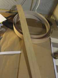
The design involved fixing wood veneer to 6mm MDF board.
I found that you could buy 50mm wide wood venner strip on Ebay:
To start I attached 4 strips of light wood and 5 strips of dark wood to stiff paper in alternate strips.
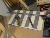
Then I cut the resulting rectangle in 50mm strips at right angles to the veneer to produce new strips of 50mm squares.
Arduino Chess board strip of squares
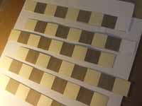
Then by off-setting alternate strips I created a chess board, which I could trim to the right number of squares and fix to the 6mm MDF. The square of MDF was 500mm x 500mm to allow for 8×8 50mm squares and a 50mm boarder all round.
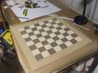
I found that adding a thin strip of edging around the 8×8 squares before the border gave the best effect. I then treated the chess board with a good quality clear sealant.
The finished chess board:
Next I drilled 5mm holes in the corner of each square to hold the LEDs.
I then wired these up in a matrix effect. I used 8 strand ribbon cable glued to the underside of the board and used an old soldering iron bit to burn off the insulation where the LEDs were to be soldered. Note that the LEDs must all be attached the same way round.The Reed switches were first glued in place on the underside of the board and then soldered at one end with a common earth, and the other end directly to the strands of 20 strand ribbon cable (16 connections, 2 common earth and 2 unused) the other end of this cable plugged directly into the Centepede card.
Note on positioning of reed switches. To position the reed switches you will first need to draw the chess square positions accuaretly on the underside of the board. The reed switches need to be placed in an off-set position so that one glass end of the Reed switch is at the centre of the square. Experiment with a test margnet to get this right or you will find the chess pieces are not recognised correctly.
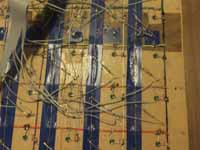
Arduino chess board wired with LEDs and reed switches
Finnaly on top of this mass of wires I fixed another thin board on battons. The wires from the LEDs and Reed switchs came round and fixed onto theMatrix controller and Centepede board respectively.
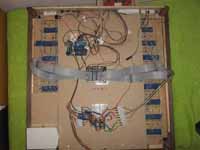
Arduino Chess Board with Matrix LED controller and Centepede board controlling reed switches
The Matrix LED controller and the Centepede then conected to the Arduino that also had connections for the display and 4 buttons which were added later.
Hi I am Waasay ‘s mom he has been corresponding with u. He started his year 12 project . He is doing his very very best and has also hired a tutor but getting error in code. This is my very humble request if u could only review his code and tell him where he is going wrong
He is very stressed and doesn’t have much time left I think hardly 2 weeks
I am traveling but will try and give some help.
First this is a complex project and requires the ability to program an Arduino and a Raspberry Pi.
Without this knowledge he cannot build this chess computer. It is not something where you just build it and run someone else’s code.
The hardware and software MUST be tested together. Sometimes errors on SW come from hw and vice versa.
This project must be built and tested in a modular fashion. I suggest the following steps.
1. Build and code the Reed switch matrix as a keypad matrix. Ie write code to detect Reed switch closes and opens using Keypad Matrix techniques. So you can detect b2 to b4
Extend this to display the position on the LCD and send as a serial port code.
This gives basic move detection.
This is the most basic of Arduino tasks and if you cannot do this, just stop.
2) Build an LED matrix controller to switch on/ off each LED given a command like a2. Extend this make sure you can receive a serial port command to receive a2 and switch on or off that light.
3) combine 1 and 2 above and extend so you can receive a command like mb2b4 which will do the following
M it’s a move
B2 switch on light on b2
Wait for piece to be lifted
Switch on b4
Wait for piece to place (or lifted and placed if already occupied)
Switch off light on b4 move completed.
4) write the reverse routine to send mb2b4 through serial port.
These are the fundamental steps of the Arduino chess board, sometimes called a USB board.
Doing just this should be enough.
If you can get this working, you can plug the USB connection into your PC and run a program like Arena Chess and it will communicate
Hey, Max! Your project are just awesome. For my college conclusion project, i’m building a Chess Board like yours, but a little different (and more complicated i believe), the one i’m making will move the pieces automatically through an eletromagnet attached under the board and the magnets attached to the chess pieces. I’m starting low, step by step, but i’m confused as how to assemble the reed switches. You have a detailed tutorial on how to assemble the Reed Switches and connect to arduino/Raspberry ?
Sorry for bothering you and thanks for you attention!
Gabriel, Your project sounds very ambitious. I hope you have a good background in Programming and electronics. I am a bit concerned that you are “confused as how to assemble the reed switches.” A reed switch is just a simple switch. You do not say if you are using an Arduino for the board or doing everything with the Pi. Doing it bit by bit is a good idea. I suggest you try and build the Raspberry PI Noughts and Crosses / Tic Tac Toe project first, even if you just build a rough version. It uses a 3×3 board so its simpler, but it still uses reed switches and Leds.
As your board uses motors, you may be better off controlling the board with an Arduino the Useful Stuff page contains lots of useful links. The most comprehensive description is on Bergers Page.
How ever you approach this make sure you build just a module at a time and test thoroughly.
Several people have built a board that moves pieces. There is even a commercial version called Square Off
Best of luck
The wiring part of the Reed Switches that i was confused haha, but those link you’ve provided are truly helpful, Berger’s one principally.
Thank you so much!
Hi.
I see, that a lot of people use for the reed switch a rectifier diode Is this necessary with your approach?
Thank you
mmm i keep reading and find that when you use the mcp23017 the diode is not necessary, i just necessary with a matrix.
mmm i keep reading and find that when you use the mcp23017 the diode is not necessary, i just necessary with a matrix.
Hi,
You do not need diodes for my design, if you want a full circuit diagram of a design with diodes see “Bergers USB Chessboard” link on the Useful stuff page or the link to “bergers page” above. If you are new to this I suggest you build the Noughts and Crosses project first, it uses all the same hardware techniques and is full explained.