
Build this noughts and crosses game first and you can build the chessboard!
This project requires only a basic ability to set up a Raspberry pi and solder electronic components, but you will learn all you need to build the chess system.
News: Lots of people have now built this project. Send me a short video and a few lines of text and I will create a “NOX Hall of Fame” (Dropbox is good)
Latest News (March 2021): This page and the associated code was written in 2017 in Python2. Since then some of the components and associated routines have become obsolete. Fortunately Fenando, has updated then (see Comments Section below)
You can find the new code at Github NOX update . You can find pictures and video at Recent Chess and NOX Machine Builds
This section gives detailed instructions for building a Raspberry PI Noughts and Crosses game, know in the USA as Tic Tac Toe, hereafter referred to as NOX. This is an ideal project to build before trying to build the chess board. It uses exactly the same components, but instead of being played on a 8×8 grid like chess, its played on a 3×3 grid. So their are many fewer connections and the game logic is simpler.
In this build I use exactly the same components as for the chess board, just fewer of them. Even the most basic builder and coder should be able to build this. When you build this you will learn useful skills and techniques so that when you come to build the chess board it will go more smoothly. This makes it a bit overkill for NOX, but a great training project.
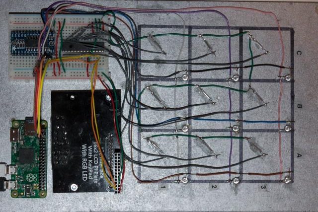
In play there will be wooden X and O pieces with magnets on the back that are placed on a board with Reed switches that register the placement. To move the NOX game will flash LEDs to show where it wants to go. The screen and buttons will indicate who’s move it is, allow setting of levels etc.
As with the Chess game the NOX game uses these components:
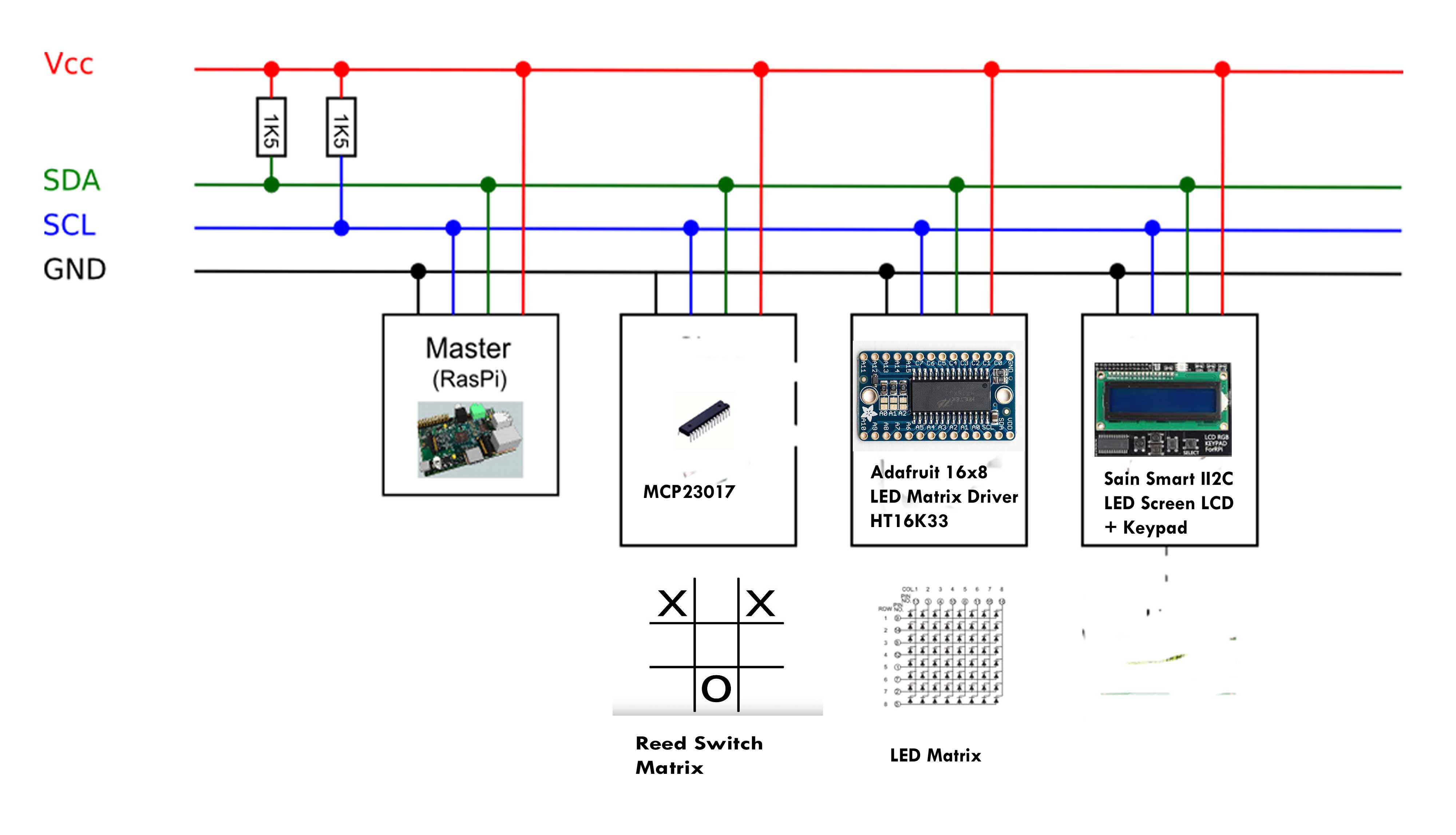
The Raspberry PI drives the other bits using an I2C bus, so there are only 4 wires to connect to the PI. You can use any PI. As this is a simple program in a small enclosure I use a PI Zero , but a PI2 or PI3 should work just as well. In this design the reed switch grid is a 3 x3 matrix which can be controlled by just one MCP23017 and the LED driver controls the 3×3 LEDs.
Raspberry Pi NOX Parts List:
| Electronic components list | ||
| 1 | Raspberrty Pi Zero | £ 4.00 |
| 1 | MCP23017 | £ 0.64 |
| 9 | Reed Switch Glass Normally Open | £ 0.99 |
| 1 | Adafruit HT16K33 16×8 LED Matrix Driver | £ 7.99 |
| 9 | 5mm LED s 5v | £ 0.64 |
| 32 | 10mm x 1mm Neodymium magnets | £ 1.30 |
| 1 | Solderless Breadboard Bread Board 400 Tie Points | £ 1.64 |
| 1 | Sain Smart I2C IIC LED Screen + Keypad | £ 6.99 |
| Total Cost | £ 24.19 | |
The prices given are just a guide. In addition you will need wood or board for the case, and wires. The wire I use is 1/0.6 single core equipment wire (not stranded wire) and I have lots of colours. Single core wire is easy to work with and can be inserted directly into a breadboard. The colours help get connections right. Single core wire is not good if it needs to flex or bend in use. Then use stranded wire.
Steps in building the Raspberry Pi NOX game:
- Prepare the Pi and load software
- Build the case
- Mount the components
- Wire the LED grids
- Wire the Reed switches
- Connect the display
Prepare the Pi and load software
I am assuming that you know how to set up a Pi with the Raspian operating system, so go to the Raspberry Pi Download page and get the latest version. If you have an existing PI ready loaded you could update and upgrade it, but I find that its quicker to re-load from scratch, especially as the new version includes VNC and I2C.
As part of the Raspberry Pi configuration make sure you enable I2C in rasp-config.
It is not vital but I find the easiest way to develop systems is to enable VNC and run the Pi headless from a PC over a wireless network.
Test you have I2c configured by typing:
sudo i2cdetect -y 1
and you should see:
pi@raspberrypi:~/$ i2cdetect -y 1
0 1 2 3 4 5 6 7 8 9 a b c d e f
00: — — — — — — — — — — — — —
10: — — — — — — — — — — — — — — — —
20: — — — — — — — — — — — — — — — —
30: — — — — — — — — — — — — — — — —
40: — — — — — — — — — — — — — — — —
50: — — — — — — — — — — — — — — — —
60: — — — — — — — — — — — — — — — —
70: — — — — — — — —
Which shows its working, but nothing is connected.
load the Adafruit libraries for Raspberry PI
>git clone https://github.com/adafruit/Adafruit_Python_LED_Backpack.git
>cd Adafruit_Python_LED_Backpack
>sudo python setup.py install
>git clone https://github.com/adafruit/Adafruit_Python_CharLCD.git
>cd Adafruit_Python_CharLCD
>sudo python setup.py install
Load my noughts and crosses files:
>git clone https://github.com/mdobres/maxnox.git
This will copy over the following files:
noxled.py tests the LED grid
noxreed.py tests the reed switches
noxledreed.py tests the reed switch with LEDs
noxfullsys.py tests all components
maxnox.py full system game
REBOOT! – always a good idea
Build the case
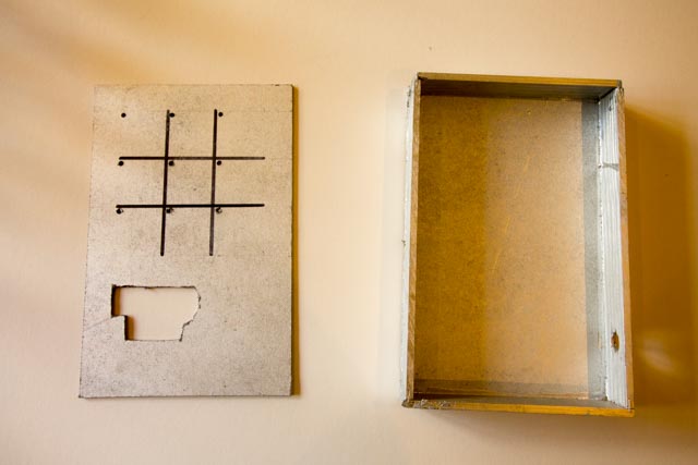
Case and front view
I am using a board with 1.75″ squares. This is a good size for the eventual chess board and makes it easy to see. I am also leaving plenty of space for the components, so the case measures 7″ wide x 11″ long and is about 1.5″ deep. The front and back are made from 3mm board and the sides from 6mm x 3mm Pine strip wood. All of which I had left over from other projects. I cut a hole for the display and then sprayed it silver.
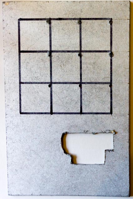
Rear of front panel
Note that the hole is a bit of a mess. This will not matter as it will be covered later with a flexible skin.
Then I drew the NOX grid on both sides checking that they aligned. This makes fixing components so much easier.
Mount the components
Solderless Breadboard Bread Board 400 Tie Points
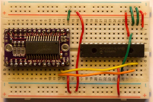
We need a way of mounting the MCP23017 and the Adafruit HT16K33 16×8 LED Matrix Driver. There are lots of ways to do this. I chose a breadboard for simplicity. It also means you can undo connections if you get them wrong or remove components if they fail. The solid core wire I am using goes straight into the connection holes and holds pretty tight.
The HT16K33 comes with legs to be soldered on, so do that first. Then position the two components on the breadboard as shown above. To make it easy to follow my instructions make sure each part is oriented as shown. Double click on the image and you will see that the HT16K33 has the cathode connections C7 to C0 uppermost in the diagram and the MCP23017 is positioned with the little semi-circle cut out to the the left.
All the Red wires are 5v Live(+) and the Green wires are Ground(-). Yellow is SDA and Orange is SDL.
The HT16K3 has labels on its connections, it has its GND connected to the (blue) Ground(-) rail of the breadboard by a Green wire and the VDD(+) to the live rail, by a Red wire. A red wire also connects the two + rails of the breadboard. The default I2C address of the HT16K3 is X70 which requires no further connection. (more on this later)
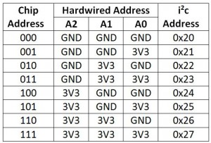
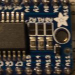
The MCP23017 first needs to have its I2C address set using pins A2,A1, A0. We want to use Address 0X21, because the Sainsmart display already uses 0X20. From this table you can see that this means connecting: A2=GND; A1=GND; A0 = + (it says 3v, but the data sheet says 5v is OK)
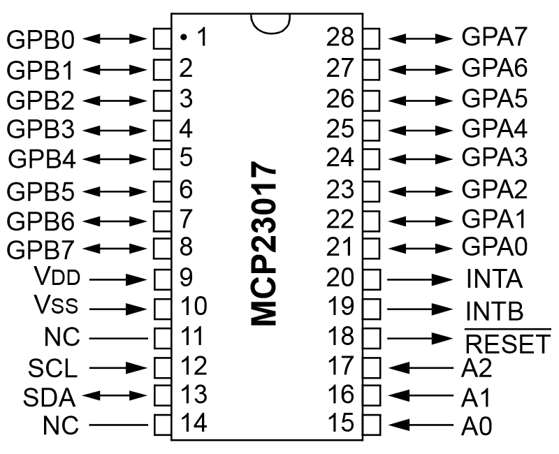
mcp23017 pinout
This pin-out chart shows the semi-circle cutout out so you can see that A2,A1, A0 are on the top right of the MCP23017 in the picture and are connected as described above to GND, GND, 5v+.
Pin 18, Reset and Pin 9 VDD also need to be connected to “+”. Pin Vss is connected to GND .
Finally SCL (pin 12) is connected to SCL on the HT16K3 (Yellow wire) and SDA(Pin 13) to HT16K3 SCL (Orange wire)
I2c Connection to the Raspberry Pi
Now you can connect four wires 5v VCC(+), GND(-) , SCL & SDA from the appropriate slots on the breadboard to the PI to test that you can see the devices. I suggest you use Red, Green, Yellow & Orange wires for clarity and consistency. I use pre-wired jumper wire for this that has one male and one female end.
Note: under most circumstances RPI pins need to be at 3v, connecting a 5v device can cause severe damage however according to Adafruit:
“Since these io expander chips use i2c to communiate, you can power them from 5V while still connecting the i2c data lines to a 3.3V device like the pi. That’s because the Pi has two i2c resistors that pull up SDA/SCL to 3.3V. Just make sure not to connect any resistors to SDA/SCL to 5V and you can power the chip from 5V (and have 5V input/output on the MCP chip). Its also fine of course to power the MCP chip from 3.3V but the 5V line on the Pi has more current capability so you might find its better to go that way.”
The Sainsmart LCD does not work well at 3v, so I have used the 5v connection and not had a problem, but its your risk.
Make sure your PI is switched off and powered down before you make the connections.
I2c Connections
Once you are sure the connections are right, boot up the PI,
get to a command prompt and type:

                                            i2cdetect -y 1

You should get:
pi@raspberrypi:~/$ i2cdetect -y 1
     0  1  2  3  4  5  6  7  8  9  a  b  c  d  e  f
00:          -- -- -- -- -- -- -- -- -- -- -- -- --
10: -- -- -- -- -- -- -- -- -- -- -- -- -- -- -- --
20: -- 21 -- -- -- -- -- -- -- -- -- -- -- -- -- --
30: -- -- -- -- -- -- -- -- -- -- -- -- -- -- -- --
40: -- -- -- -- -- -- -- -- -- -- -- -- -- -- -- --
50: -- -- -- -- -- -- -- -- -- -- -- -- -- -- -- --
60: -- -- -- -- -- -- -- -- -- -- -- -- -- -- -- --
70: 70 -- -- -- -- -- -- --
This shows that you have two devices connected to the Raspberry PI I2C bus with address 21 (MCP23017) and 70 (HT16K3). Congraulations! How Shutdown the PI and carry on with the next stage. If you get a 71 instead of a 70 read the note at the end on issues.
Wiring the LEDs
Now we wire the LED matrix. First drill holes, insert the LEDs and identify the longer “Anode” leg of the LED and bend it so its horizontal as in this picture, then when you solder the vertical wires they will join all the Anodes. So in this picture the pink purple and white wires join anode legs and connect to A0, A1 & A2 on the HT16K3. The you solder the cathodes to wires that go to C0, C1 and C2 on the HT16K3. When you are done trim the LED wires back to the solder joint as shown.
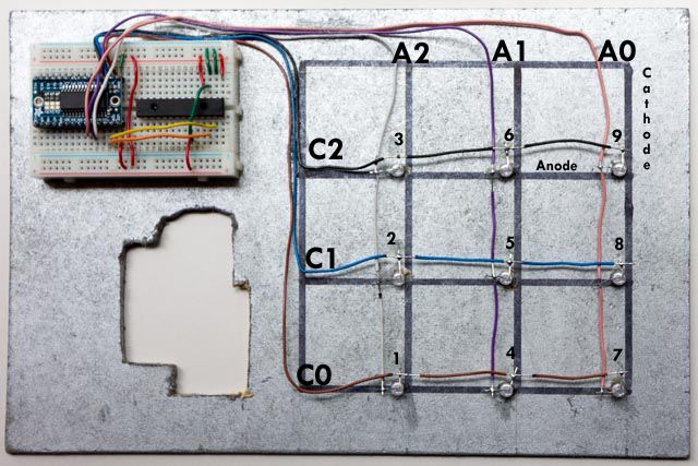
A note on wires: You will see that the wire is only exposed where it is soldered onto the LED leg. We need the insulation to protect from other crossing wires. I found a neat way to do this. so you get the gaps in the right places.
Now we can test this matrix by connecting our Raspberry Pi with the four I2c wires and running the python program noxled.py. If it all works you will see the LEDS light one by one in the order 1 to 9 as shown above. Try and get then all to light in the right order by checking the wiring, i.e. that the correct wire goes to the correct connection on the HT16K3 as the other program use this to match with the reed switches and game logic. If no LEDs light you may have got the Anodes and Cathodes of the LEDs round the wrong way.
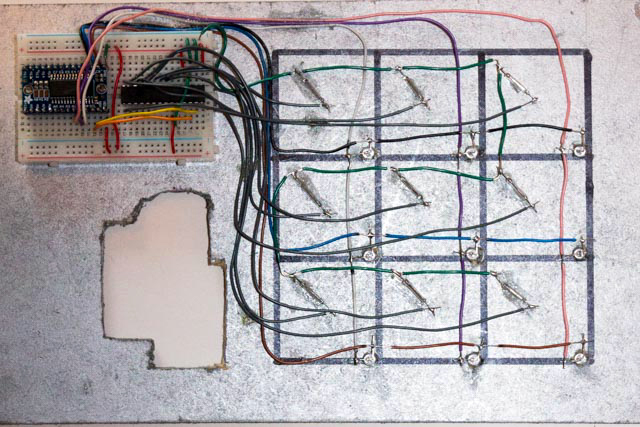
Wiring the Reed switches
The Reed switches are connected to the MCP23017 see pin-out above. Each Reed switch has two connections. One end goes to a common Ground , the other end goes directly to one of the connections GPA0-A7 (pins 21-28) and GPB0 (pin1). It doesn’t matter which end of the Reed switch. The first step is trim the Reed switch legs and glue the Reed switch to the board. Note the position, not in the centre, but midway on a half diagonal to the corner as shown below. Then solder an Ground wire that connects the ends of all the Reed switches to the Ground rail of the breadboard. Prepare the wire using the method described in Tips & Techniques, so that it the insulation is only bare where it needs to be soldered.
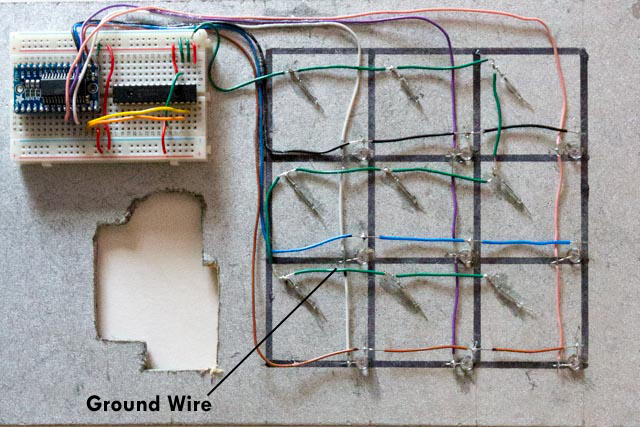
Next we connect the other end of each of the Reed switches directly to the MCP23017 connection on the breadboard.
Using the 1-9 numbering in the LED diagram the connections are:
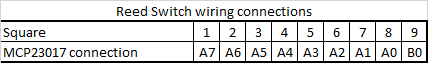
And when its done it looks like a load of spaghetti, so be careful to get the connections right. At least using a breadboard you can replug if you get them wrong.
When you think its right connect your Raspberry Pi with the four I2c wires. Run
i2cdetect -y 1
to check you still see both I2c devices, then run the python program noxreed.py. Stick one of the magnets on a spare bit of wood and hover it over a Reed switch. The Switch is “normally open” so when you place the magnet it closes and when you remove it, it opens again so when you put the magnet near the program will display a message on the console:
Square 7 Reed switch close
when you put the magnet over the switch and
Square 7 Reed switch open
when you remove it.
Test for synchronization of reed switches and LED
If that works run
noxledreed.py
Then move your magnet over the reed switch. If its all connected correctly this will light the LED for that square as the magnet closes the reed switch and switch off the LED when the magnet is lifted. If this works, you’ve done the hard part. Congratulations!!
Connect the I2C LED Screen + Keypad
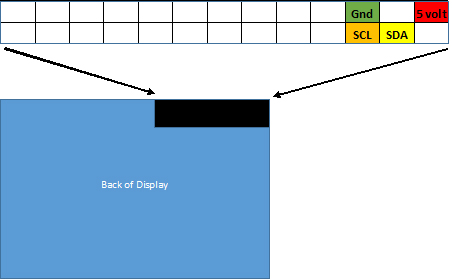
Shutdown and power off the Pi and now fix the “Sain Smart I2C IIC LED Screen + Keypad” to the front panel (I used bolts) and connect the four wires 5v VCC(+), GND(-) , SCL & SDA from the appropriate slots on the breadboard to the display as shown.
Everything Connected!
Connect your Raspberry Pi with the four I2c wires. Run
i2cdetect -y 1
You should now see three connected devices at 0x20, 0x21 and 0x70. The display and keypad is 0x20. In fact its controlled by a built in MCP23017.
To test the display just run the example program that came with the software you downloaded earlier. Its in the directory
pi/adafruit/Adafruit_Python_CharLCD/Examples
and called
char_lcd_plate.py
Run this and it tests the display and all the buttons.
Now run this final test program that tests all three components. When you place a magnet on a square it lights up and the square is identified in the display.
noxfullsys.py
If that works you are ready to put the finishing touches to your project and run the maxnox.py application.
Finishing Touches for the Raspberry PI Naughts and Crosses / Tic Tac Toe
Now we need to just finish off by installing a skin over the keypad/display to tidy up the front. This template
can be laminated using a home laminator and then fixed to the front cover as shown to give button labels and cover the rough hole. If you do this you will find there is a gap between the cover and the buttons. Fix this by gluing 8mm shirt type buttons to the back of the template as shown. Don’t glue them to the LCD buttons, you can easily glue then shut that way.
You will also have to decide how you are going to power this. You could build in a battery pack or just have a USB connection on the side as I have. I leave that to you.
If you are keeping this as a permanent project you should work out how to get the program to start at boot.
If your Raspberry PI Naughts and Crosses / Tic Tac Toe system is working you now have all the skills and knowledge you need to build a Rasperry Pi chess system. The components are the same, there are just more of them.
Issues:
Before
HT16K33 LED Matrix Driver
When we type this should show up as address ox70. However I got a faulty one that
swapped between 70 and 71. I checked with Adafruit and they said it was a faulty resistor and the address floated so they sent me a new one.
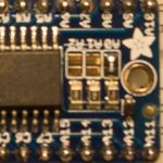
Solder blob on A0
I fixed this by forcing the address to be ox71 permanently by using three A0, A1 A2 solder jumpers. Each one of these is used to hardcode in the address. By bridging jumper A0 with solder it adds 1 to the address making it 0x71. This seemed to work.
Next I then edited the line that defines the address in code:
display = Matrix8x8.Matrix8x8(address=0x70, busnum=1)
to change address=0x70 to address=0x71
Pi Zero
I had a very old Pi zero that I bought the day they came out. I loaded a copy of the latest operating system and when I typed i2cdetect -y 1 I got a blank grid (so the software worked) even though devices were attached. I put the same SD card in a newer Pi zero and it worked fine. Checking on the internet others seem to have had the same problem.
Hi,
in the SolusChess project the problem with the “ghost key” effect was described. That is why one should use a signal diode for each reed switch. Don’t you have such an effect or is there a reason you didn’t used those signal diodes?
Viktor, the SolkusProject uses the Reed switches arranged in an 8×8 matrix, so the “ghosting” problem can occur because other chess pieces on the board close switches and provide other routes to each switch. The Diode stops this. In my design each Reed switch is wired directly to a port on the MCP2307 so there are no alternative routes and no need for the diode.
Hi,
I am trying to build the chessboard using Raspberry pi and MCP23017 only. Can you please upload your code to github for chess project (just like you did for this project)?
It will be helpful.
MS, My original working Chess board is Arduino based linking to the PI running the chess engine, and I have not finished the code for the full Pi version yet, I keep getting side tracked. So the only working code I can offer is the NOX code. Also have a look at Brian’s page and you will see he has a full download there.
Max, thank you for the project. I have nothing to do with this matter but chess! And I work at the evening and the weekend at my nox pi 😉 next step is to mount the lcd and run the tests! Never soldered anything before! Never used python, never had a Raspberry pi…. Thank you very much for this great project! You have to know that I am waiting for your update to raspberry pi only code/project. I was so sad when your site was down yesterday! One question: how long should the reed switch be for 5 cm square or should I just use bigger magnets? Cheers, Fritzmann
Hi, I use the same standard Reed switch for the chessboard as I do the NOX system. the key is to place them off centre as described. Pi only code still on the back-burner I am afraid.
Hi Max – re: NOX issue with LED Backpack
I have no problems with the reed switch matrix/MCP23017. noxreed.py works fine.
I have tried everything I can think of to get noxled.py to work. after several weeks I apparently have a write error I cant solve.
pi@Pi_Zero_2:~/maxnox $ sudo python noxled.py
Traceback (most recent call last):
File “noxled.py”, line 37, in
display.begin()
File “build/bdist.linux-armv6l/egg/Adafruit_LED_Backpack/HT16K33.py”, line 53, in begin
File “/usr/local/lib/python2.7/dist-packages/Adafruit_GPIO-1.0.3-py2.7.egg/Ada fruit_GPIO/I2C.py”, line 127, in writeList
File “/usr/local/lib/python2.7/dist-packages/Adafruit_PureIO-0.2.1-py2.7.egg/A dafruit_PureIO/smbus.py”, line 274, in write_i2c_block_data
IOError: [Errno 5] Input/output error
I have reloaded (several times) the latest OS, firmware, update, etc. Followed all your direction wrt Adafruit files, etc. Using 0x72 as I2C address and updated in the sketch. Read all the Adafruit info, switched backpacks with I2C address of 0x70, etc.
No, I am not proficient in Python, most of my coding experience is in embedded C for ARM micros (worked in sales and marketing for 35 years with Philips/NXP). Played around with Arduino’s, Beagle Bone’s, all versions of RPI since v1. I really want to move ahead successfully because my goal is to build your chess project – but I am stumped. As a retired BSEE, I feel somewhat chagrined I cannot solve this technology hiccup I must have.
tks&rgds/jack
Thanks for posting your work.
Jack, my initial view is that this a failure to read and detect the HT16K33 I have had a few problems with them. First make sure that the HT16K33 is set to the address in the python program. Assuming it is try checking that the Pi is seeing the device by running the command sudo i2cdetect -y 1 immediately before and after the python program fails. I have had cases where the address becomes unstable and changes. In fact run this command a few times before and after. Also try it with only the HT16K33 connected, no other devices. I will try and dig deeper over the next few days. Also a word of caution, My original chess project shown in the video used an Arduino to run the board and a PI to run the chess engine. Version 2 was designed to dispense with the Arduino and do it all with the PI, however I an struggling to get all the I2c devices to work at the same time even using a Mux. I will persevere, but I am beginning to wonder if the Arduino might be a better bet
Hi Max, sorry for the delayed reply. Still working the NOX issues. I ordered a RPiZeroW and waited to try everything with a new install, etc. Started from scratch, redid the breadboard, etc. Installed the backpack per Adafruit. Ran i2cdetect -y 1 several times before and then again after trying to run noxled.py. The HT16K33 is only connected. (I note that the noxreed.py will not run with the HT16K33 and the MCP23017 both connected to the bus, but the program runs fine with only the MCP23017 connected). I still get the following error messages. I have another HT16K33 set to I2C address 72, changed the address in the sketch, same result. i2cdetect sees it as 72, but same error feedback. Is there a file location issue? I haven’t even gotten to the LCD yet, as they are back ordered for weeks from Adafruit. (The generics I ordered from eBay/China were not worth the wait …. 🙂
I’ll keep trying, as I can’t let this beat me. Gotta be something simple I’m missing ….. is there a difference in using Idle 2 vs Idle 3? I believe you are using Idle 2 based upon the print statement format ….
tks&rgds/jack
Traceback (most recent call last):
File “/home/pi/maxnox/noxled.py”, line 37, in
display.begin()
File “build/bdist.linux-armv6l/egg/Adafruit_LED_Backpack/HT16K33.py”, line 53, in begin
self._device.writeList(HT16K33_SYSTEM_SETUP | HT16K33_OSCILLATOR, [])
File “build/bdist.linux-armv6l/egg/Adafruit_GPIO/I2C.py”, line 127, in writeList
self._bus.write_i2c_block_data(self._address, register, data)
File “build/bdist.linux-armv6l/egg/Adafruit_PureIO/smbus.py”, line 274, in write_i2c_block_data
self._device.write(data)
IOError: [Errno 5] Input/output error
Jack, you need to use IDLE 2 for my code to work as it’s written in Python 2. If you use IDLE 3 you are using python 3 which has a different syntax. That may also apply to the Adafruit libraries. If this does not fix the problem I suggest you go to the Adafruit HT16K33 tutorials to make sure the libraries are correctly installed
Thanks, Max. I am using Python 2 for everything. I have installed per Adafruit several times, on new Jessie installs, and updated user space and firmware. Unless the 2 backpacks I have are flawed, I’m clueless. I have ordered a couple more to try just in case. Appreciate your time to respond. Will only get back if I have any future success.
rgds/jack
Jack, suggest you go back to basics, make sure that after you issued:
git clone https://github.com/adafruit/Adafruit_Python_LED_Backpack.git
you then installed the LED backpack by
>cd Adafruit_Python_LED_Backpack
>sudo python setup.py install
Then do a
sudo i2cdetect -y 1
Can you see the device?
If so try one of the adafruit examples by settting up a simple 3×3 LED matrix on a breadboard.
The errors you are getting suggest the backpack is not connected
Try all this with a 3v connection.
Also try it all on a different PI, its possible you have damaged the I2c pins.
Hi Max – yes, I have previously tried 3.3V, a RPi Zero, ZeroW, B+, and a 2B. Same result, as well as 2 different LED_Pack. Rewired the breadboad several times, BUT I ALWAYS USED THE SAME POSITIONS FOR THE IC AND LEDPACK. One of those 830 socket solderless PCB terminal types (a double length one like yours in your article). Tried another one on a fluke fried brain no farpin way it could be bad, wired it exactly the same – everything works, on all the RPi’s, both LEDPacks. Last thing I would have thought (obviously, it was indeed the last thing ….) was a bum breadboard. The hours I wasted …
In any case, thanks so much for your insights and help. Your code is perfect. Glad I didn’t give up. Still awaiting the LCD backpack, but after that on to the chess board challenge……
rgds/jack
rgds/jack
Hey Max,
Appreciate the work you put into documenting this project. I am unable to test the LEDs the import error I am getting is: No module named Adafruit_LED_Backpack
( When I go to run noxled.py )
Any help would be appreciated,
Thanks
Jeff,
It looks like you may have missed some of the steps in the section:
“load the Adafruit libraries for Raspberry PI” above . You need to load the software using git clone, go to the target directory and then run the install program
>git clone https://github.com/adafruit/Adafruit_Python_LED_Backpack.git
>cd Adafruit_Python_LED_Backpack
>sudo python setup.py install
Appreciate the quick reply. I did some homework and realized cd means change directory. The install was successful, tested noxled.py LEDs work. Thank you!
Hello Max,
Absolutely thank you so much for posting this guide. I got to the part where I had to test noxled.py. Apparently every time I run it, I keep getting this error,
pi@raspberrypi:~/maxnox $ python noxled.py
Traceback (most recent call last):
File “noxled.py”, line 37, in
display.begin()
File “build/bdist.linux-armv7l/egg/Adafruit_LED_Backpack/HT16K33.py”, line 53, in begin
File “build/bdist.linux-armv7l/egg/Adafruit_GPIO/I2C.py”, line 128, in writeList
File “build/bdist.linux-armv7l/egg/Adafruit_PureIO/smbus.py”, line 274, in write_i2c_block_data
IOError: [Errno 121] Remote I/O error
I tried re soldering the wires and made sure I installed the packages correctly. Any tips on what the issue might be?
Thanks
Michael,
Sorry I have not touched the code for a year or more so I am not sure what is going on. It sounds like the noxled cannot see the HT16K33.
Have you run i2cdetect -y 1 and can you see that device “70” the HT16K33 is connected.
Re-check the install. Did you run the line “sudo python setup.py install” and the other similar one.
Otherwise you may need to try some of the Adafruit examples to check you can connect and use the device.
You will see from comments above that Jack Fuller and Jeff also both had similar issues, but they were resolved by rechecking they had precisely followed the instructions.
Best of luck
Max
Hi,
Me and my buddy are doing our final year of gymnasium and we chose this as our final hand in work. We have done every step without failiure up until trying noxled.py, we get the error message “Import error, No module named Adafruit_LED_Backpack”. We saw that another person in the se comments had the same problem but the solution that worked for him didnt for us. We are not very skilful when it comes to python and all the code. We are using a raspberry pi model b v1.2. Would appreciate if you could help, if u can and know how to.
Best regards
Niklas and Anton
Niklas, Sorry have not looked at the code for nearly 2 years, so not able to help. I would not suggest this project to those who are “not very skilful when it comes to python”
I remember there is a particular way the Adafruit_LED_Backpack needs to be installed and it sounds like you may have missed something. I would suggest going through each step carefully and also going to the Adafruit website and tring to install their example system.
Could I not install the version of raspbian that you were using, redid the installation carefully many Times and im certain that ive done it the correct way. I feel like it has to do with python 2 to 3 compatobility issues since the code is written in python 2 and we are using python 3.
Hello,
I like to prepared a smart chess board. I have gone through your ideas. I have still one query that did you have used both Arduino and Raspberry PI.
where, Arduino is used for motor or actuator moment. And Raspberry PI is used for logical move.
Can you say me the h/w part number has been used by you.
Also how did you communicated Raspberry PI with Arduino.
Thank you in advanced.
In my first design I used an Arduino to control the board and an RPI to run the chess engine. I used a simple serial communication between the RPI and the Arduino. Almost any Raspberry Pi and Any Arduino will work.
Hi.
“I finished” the tic tac toe, since I don’t have a display with buttons, I forgot that part so I can only test the python files until the part of the led functionality with reed switch. And that is barbaric.
It will be possible, that you hang up the code to be able to play without having to select level, presentation or anything, so when I run the program start playing? (Because, just having no buttons I can not choose, I do not care if I can not choose who plays first or anything, it would be just to enjoy it a touch).
Thanks for all your work! Next… the CHESSSSSSSS!!!
Hi. Me again… sorry for all the question. Well, i have this kind of LCD https://cdn3.volusion.com/btfzd.umflq/v/vspfiles/photos/157-2.jpg?1463420857
Without the buttons. I try to use it, but, i found that the code dosent work (probably because this is another kind of lcd). Can you give me a hand to solve this??
Thanks.
And.. here i am again, im
I change some things in this file: ~/Adafruit_Python_CharLCD/Adafruit_CharLCD /Adafruit_CharLCD.py
I change address and cols and lines (for my address that is 0x27, and cols 20, lines 4)…
And now i dont get a error when i run maxnox.py… but… the display turn on and off whe n i put the magnet in a reed switch.
So i dont know what to think must that the pin on the Adafruit file are wrong for my display… but how i can change those values??
In the other hand i follow this http://hardware-libre.fr/2014/03/en-raspberry-pi-using-a-4×20-characters-display/ and with that i run the test file “hello world”, and that works perfect.
It will be because i dont have buttons in my display?? or will be the code refering the pins??
Thanks for your help.
And… this is my display (2004a) datasheet:
https://ufile.io/wuvh309a
With a backpack pcf8574
Hi. I already change the code about the display. Now i have to reconstruct all the thing about the menu…
Im posting this, just you read this, so you know that now im with another problem.
Thanks and sorry for my message.
Hi Max, maybe you can help me or at least tell me if there is errors on purpose.
Is working now, but….. not completely.
The display is working, the button (i just put one for “yes”) is working.
But something strange happend. The game just let me put a piece on the square 8 (counting from 0-8), only there recognizes the piece.
Then the game tell me “Making my move place piece”. And there (i play en expert mode and always says square 4, the led start tu blink), i put then the piece in square 4. So it’s time for my move, but the piece does not activate the switch in any other square.
And, that is really strange because, for example let says that no interrutor works except those. So why i cant place my move in square 4??? (i just can only put my piece in square 8).
In the other hand, i test all whith the little programs
And, all is working fine:
noxled.py —test just led-works ok.
noxreed.py —test just reed switch- works ok.
noxledreed.py—(this is for test the reed switch and led)–again works ok.
I dont know why you change the numbering system
90 w=sq+1 # different numbering system
(this is different to noxledreed.py)
In the other hand what is “sq”
89 def ledon(sq):
Maybe in that place are the errors?
I really dont understand.
Thanks for your time.
Hello,
May be I’m a bit late… but let me try.
I have loaded and installed the Adafruit libraries for Raspberry PI as indicated.
Everything is OK until the LCD test.
I see three connected devices at 0x20, 0x21 and 0x70.
The display and keypad is 0x20.
But when I test the display just by running the example program (char_lcd_plate.py) that came with the software downloaded earlier, it doesn’t work.
It run, test the display and led, and all the buttons without lighting the LCD. I can read (with difficulties!) message sent on the screen.
Does anyone have ideas?
Thanks for support.
Finally LCD was out of order! 🙂
hello Max, thanks for sharing it here, me and my kids are trying to do this when schools is closed becouse of covid 19. we couldn’t get Sain Smart I2C IIC LED Screen + Keypad, can you suggest any alternative please, thank you
Hi, have not looked at this for years but the “ Adafruit 16×2 LCD+Keypad Kit “ should work especially as they produced the software utilities used on the NOX project. Note that this is a KIT so will need assembly. A couple of UK places have them.
Good day mate and thanks for a quick reply, found this one from Aus, will it be okay?:
https://au.element14.com/adafruit/1115/blue-white-16×2-lcd-keypad-kit/dp/2279959
please reply.
Should be OK, the tech spec says its I2c which is the important bit. It all depends if the original Adafruit libraries still work.
The other point to watch out for is the python version. I used Python 2 and therefore IDLE 2 for my code to work as it’s written in Python 2. If you use IDLE 3 you are using python 3 which has a different syntax. The original Adafruit libraries were also written in Python 2. However from some of the above comments it looks like this should still be OK. Best of luck
Thanks Max, nothing we can do in this COVID 19 days, schools, shops are closed. Can you also please upload some other projects with rpi, kids are interested it. have a good day.
Sorry I don’t have any other projects documented. The best place to go is raspberrypi.org which has lots of resources aimed at kids including projects, courses and their free Magpi magazine.
Hi!
I could not find the SainSmart I2C IIC LED Screen + Keypad online and I was wondering where you got it from and if you could provide me with the link.
You might try the Adafruit version , which should work. But I have not tested it and small differences may stop it working. Note that this is a kit and will required soldering to assemble. There are other “I2C IIC LED Screen + Keypad” shown on Ebay that are ready assembled and some look just like the SainSmart ones, so there is a good chance they might work, but no guarantees. The important part is that they use the I2C interface.
Hi Max,
Thank you for your time, Could n’t get connected rpi and MCP2307 and HT16k3, please elaborate the connection from the breadboard to rpi;
Hi, the connection is fully explained in the section marked “Mount the components”
Hi Max,
I hope you are doing very well!
I just finished the NOX project and it is up and running. Thanks for your detail explanations and recommendations. This was my first project with electronics and microcomputers. I used the same components as you listed below and step-by-step procedure. The main issued I had to deal with was that the python_led_backpack and adafruit_python_charLCD libraries are no longer valid and the new ones do not work on python2 which is no longer supported. Therefore, I had to modify your code slightly to accommodate the new libraries and update the code for python3.
Here are the steps I followed for installing the new libraries from command screen (using linux commands).
1. Raspberry PI Preparation
>sudo apt-get update -y
>sudo apt-get upgrade -y
2. Enable the I2C Interface
>sudo raspi-config
a new screen will pop up. Here you will need to select I2C Enable
3. Install adafruit-blinka (to allow the adafruit libraries to work)
>pip3 install adafruit-blinka
4. Test the I2C Bus
>lsmod | grep -i i2c
here you should see:
i2c_bcm2835
i2c_dev
This indicates that the I2C module is working
5. Search for all peripheral address to make sure there are communicating with the I2C
>sudo i2cdetect -y 1
here you should see a matrix table similar to the one shown above by Max with 3 addressed (LCD is OX20, HT16K33 is OX70 and MCP23017 is OX21
6. Install the new HT16K33 library
>pip3 install adafruit-circuitpython-ht16k33
7. Install the new CharLCD library
>sudo pip3 install adafruit-circuitpython-charlcd
8. Test the LCD 16X2 using the adafruit file
charlcd_i2c_rgb_simpletest.py
The LCD test file is stored in your raspberry directory where the LCD library is installed. In my raspberry it is located as follows
/usr/local/lib/python3.7/dist-packages(6.2.2)
Once you have installed the proper libraries and run the updated test files the NOX game will work.
The main issues I had was with the reed switches that broke very easily and the sainmart LCD which has a very poor brightness. Apparently a resistor is not working properly. I also had the issue reported by Max with the HT16K33 address changing form OX70 to OX72. If you keep trying it will reset by itself or you can try the procedure mentioned by Max above.
Finally, Max, I have some pics of my project and a video that I can send to you. Please let me know where I can post them. I also have the revised code for all your files in case you want to post them into your git account.
Again, thanks very much for this such a wonderful project.
Fernando, good job modifying and updating the code. Others will benefit from your work. If you send me the pics & videos and the revised code in a zip file I will work out the best way to provide access. I will contact you directly by email. Will you now go on to build the chess board?
Hi Fernando, thanks for your input here, would like to ask you a question,
did you used Sain Smart I2C IIC LED Screen + Keypad?, It is not available in my region so I used Adafruit Blue&White 16×2 LCD+Keypad Kit for Rpi. It need lot of soldering and found complicating for me, so I lost my interest.
Once I solder all of the parts of the LCD kit, could n’t get connected with rpi, so it made me mad and I don’t know what to do?, any help in this appreciated.
also please upload some videos on youtube about it, thank you again
Thank you.
Hi Max,
I’ve sent you the code, an pics. The video was to large for compressing, so I sent you the link to a youtube address where you can see it. Feel free to post them in your site if you find them useful. I do plan to build the chess board down the road. Where you able to build the new chess board with the 4x MCP23017, HT16K33 LED Driver and Adafruit TCA9548A I2C Multiplexer? I don’t foresee a problem with the wiring and hardware. It’s very well-explained in your site. I just need to build the interface the interface between stockfish and the board and this is where I may need some help. I’ve noticed a lot of comments on that in your site, so eventually I will figure it out. I will keep you posted. Thanks. Fernando
Fernando, thanks I have loaded the pics on the site and uploaded the code to Github as a branch. See note at top of this page