The goal of this new project is to build a fully functioning Wooden chess computer (Like a Mephisto Exclusive) similar to the one described in this site, but in a simpler way and in a way that others can copy. It is important that the design produces a wooden board that is nice to look at and use.
You will see from the Recent Builds page. That Fernando has got this design working.
Design goals:
- Raspberry Pi based, no other processor
- Simplicity/ ease of build.
- Low cost
- Ease of duplication by others.
New Easy to build Electronic chess board design!
Since I first built this project the Raspberry Pi environment has exploded and many new bits of hardware and software modules have been developed. The net result is that it is now easier to build a system using just the Raspberry Pi (without an Arduino) and the alternatives to the Pi such as the Beaglebone Black make no sense. The arrival of the Pi Zero for $5 strengthens the case.
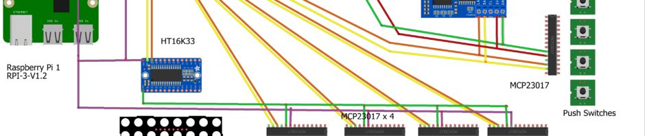
I2c bus connects all major components
I2c Based design with multiplexer, only major connections are shown Note: Red wire is 5v and the purple wire is 3v, Green = Ground, Yellow = SDA, Orange= SCL
My original design had assumed I could use a single I2c bus and hang all devices off that. It turns out that while it is logically possible to connect a very large number of devices to the Raspberry Pi via I2c, It is not electrically straight forward. Many I2c devices are supplied on breakout boards with built in resistors, and devices may run at either 3v or 5v.
The 5v devices usually run displays. The net result of all of this is that in practice you can only directly connect 3 devices reliably without carefully balancing voltages and separating out devices with different voltages.
I found that with the device mix need for this project that I got intermittent failures because of the load place on the bus if 4 or more devices are attached. So the noughts and crosses project worked fine, but this chess project requires a slight adjustment.
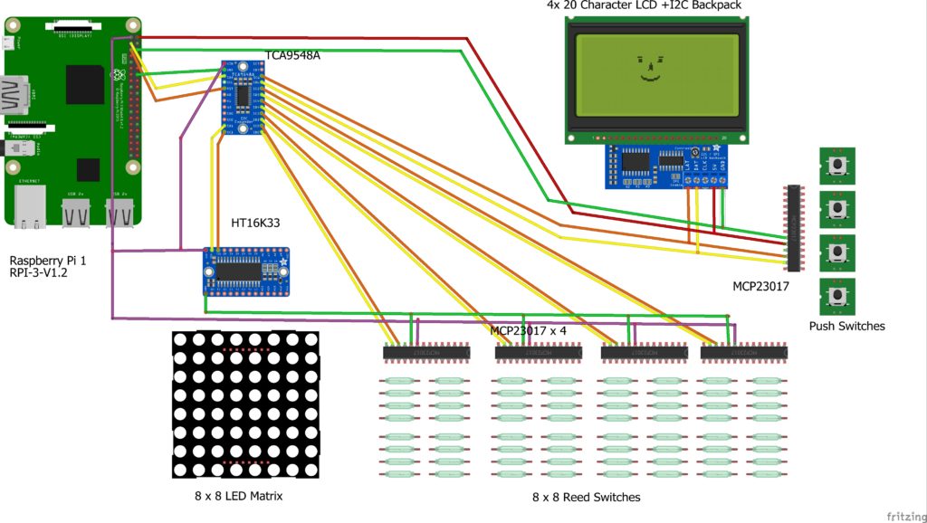
The solution, is to connect a TCA9548A I2C multiplexer to the PI and then connect up to 8 devices to the multiplexer. This gives you 8 I2c channels to which each component is connected. All that is required is a small change to the original software. I am building this variation now and will include more detail when its done and tested.
9th December Update:
I have now tested the TCA9548A I2C multiplexer with all devices and it works well and simply. You connect the mux as if it were a 3v I2c device using 3v, Gnd, SDA and SCL.
It normally has an I2C address of x70, but I changed it to x71 by simply taking A0 to 3v, this avoided a conflict with the HT16K33 which is also x70.
On the output side, you connect each device to its own 3v or 5v supply, plus GND and then connect its SDA & SDL leads to whichever of the 8 channels you choose. ( 0 to 7)
You start your code with these lines to set up the mux:
import smbus
I2C_address = 0x71
I2C_bus_number = 1
bus = smbus.SMBus(I2C_bus_number)
Then before each device you tell it which <12_channel> 0 to 7 to use by using:
bus.write_byte(I2C_address,i2c_channel**2)
the “2**i” calculates binary that gives channel pos, ie channel 0 is 0b00000001 (first channel along) and channel 4 is 0b00010000 (5th channel)
Importantly you don’t change the I2C address of any of your devices from what they were before, except where they might clash with the MUX, in my case no “0x71” allowed.
The great advantage of this device is that:
- You can have up to 8 channels, but the load on the Pi is as if one is connected.
- You can use devices with a mixture of 5v or 3v powered directly from the Pi without the need for a logic level converter.
- Devices can have duplicate I2c addresses provided they are on different channels, the only reserved address is the Mux address.
The only exception to this good news is the Sain Smart I2C LED LCD with Keypad that I used for the noughts and croses project. Unfortunately the Adafruit library it uses seems to have hard coded bus routines in it and I cannot figure how to edit it. I have also decided I want a bigger screen so I am going for an I2c 4×20 Character LCD, which I have tested with the mux and it works, plus another MCP23017 for the four buttons I need.
My next step is the final assembly of all this, however I am off for a month or so soon, so it may take a while before I get around to it.
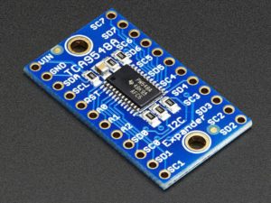
Adafruit TCA9548A 1-to-8 I2C multiplexer
My new design uses the I2c bus. This means that it connects to the Raspberry PI using just 4 wires. It consists of these elements
- Raspberry Pi (any model including the zero)
- TCA9548A 1-to-8 I2C multiplexer
- 4 x MCP23017 I2c Port expander controlling 64 reed switches
- Adafruit 16×8 LED Matrix Driver Backpack – HT16K33 Breakout**
- Display: I2C 20×4 Character 5v LCD Display
- Buttons: 4 Push switches connected to another MCP23017
Another advantage of this design is cost. The total cost of all the electronic components is shown below. All except the Pi, sourced on Ebay, mainly from China, more expensive if bought locally.
| Item | Price £ | |
| 1 | Raspberry Pi Zero (But any pi will work) | 3.00 |
| 1 | TCA9548A 1-to-8 I2C multiplexer | 6.34 |
| 5 | MCP23017 port expanders | 4.00 |
| 64 | Reed Switch Glass Normally Open | 6.93 |
| 1 | Adafruit 16×8 LED Matrix Driver Backpack** | 1.54 |
| 64 | 5mm LED s 3V | 3.20 |
| 32 | 10mm x 1mm Neodymium magnets (for the pieces) | 4.39 |
| 1 | I2C 20×4 Character 5v LCD Display | 4.00 |
| 4 | Push Button Switches | 4.00 |
| Total Cost | 37.40 |
I will put up more details of the build later, but the connection each of the components above is well documented on the web.This does not include the cost of the chessboard & pieces.
** I used to list the generic HT16K33 board, but I had problems with it. So I think it better to use the Adafruit 16×8 LED Matrix Driver Backpack – HT16K33 Breakout, particularly as they have written the driver for it.
Software
The software for each component is broadly the same as described elsewhere on this site and I have got all the components working separately. I am currently working on finishing the hardware build. Whatever way you design it there are still 64 reed switches and 64 LEDs to solder in place.
Controlling the Reed Switches is here
Controlling the LEDs can be done with the Adafruit 16×8 LED Matrix Driver Backpack – HT16K33 Breakout it has its own library, which makes programming in Python very easy.
Software that uses the MUX
All the hardware elements work together and have now been tested. I am now in the process of completing the physical build and will then modify the chess software for the PI only build.
In the next few weeks I will publish test software for these Mux elements, but as a taster here are two test programs. Both use the Mux. One tests the 4 MCPS by printing to the monitor the state of a chess board switches eg A1 Open or E4 Close. The other does the same thing, but also turns on and off the corresponding LED using the HT16K33
The Physical Build
I have described elsewhere the basic approach to building my first chessboard. Here are some further topics on the subject including a welcome contribution from Brian.
Connecting the I2C Hardware
First connect the TCA9548A I2C multiplexer: directly to the PI as if it were a 3v I2c device using 3v, Gnd, SDA and SCL.
It normally has an I2C address of x70, but I change it to x71 by simply taking A0 to 3v, this avoids a conflict with the HT16K33 which is also x70.
Check by typing: sudo i2cdetect -y 1
You should see one device connected with address x71.
You will see that the MUX board has 8 channels labelled 0 to 7. Each channel is a pair of SDA and SDL connections.
Our Connections will be:
| Channel | Device | I2c Address |
| 0 | KCD Screen and Keyboard | 0x3f, 0x20 |
| 1 | HT16K33 | 0x70 |
| 2 | MCP23017 Chess col A,B | 0x21 |
| 3 | MCP23017 Chess col C,D | 0x22 |
| 4 | MCP23017 Chess col E,F | 0x23 |
| 5 | MCP23017 Chess col G,H | 0x24 |
Now connect each of the 4 MCP23017 s to one of the channels by wiring the SDA & SDL leads to the Mux connection as shown in the table above. ie One MCP to one channel. Connect the power and Gnd cable to the 3v and Gnd pins on the PI.
Configure the MCPs to the correct I2C address from the table. see the NOX page for how to configure I2c Addresses.
I suggest you do one MCP at a time, or at least just do one to start with. You can modify the test code in MuxMaxAllMCPV2.py. There are two loops for the MCP, one for set-up and the other for scanning. of the form
for i in range(0,4): # for each of the 4 MCPs
# read the 8 registers
for k in range(0,4):
Change that so for the first MCP it reads i=0 and k=0 (i and k are not the channel numbers, you will see that the program adds “2” to each)
Note that if you run sudo i2cdetect -y 1 now, it will still only show one device at x71, the Mux.
The I2C signal is switched through the mux by the program to the correct channel preserving the I2C address of the device so that the device recognizes the call. As all the MCPs are on different channels we could have given them all the same address, but I made them different so you can test without the Mux if you want to and for clarity.
Hi Max,
An idea for the enclosure. I went to a web site that offers tailored enclosure at reasonnable price ~50€ including transport for a 50*50 cm with a specific pattern. Possibility to choose the type of wood (oak, beech) & pattern.
http://www.soclebois.fr/ (sorry in French)
I requested if possible to keep only the sides (the central part being dug) and that was possible at same price.
Olivier
Interesting, Are you expecting them to put a chessboard on the top?
Hi Max,
Yes. I have bought a chessboard and will dig the inner part for the reeds. Then I think of just putting it onto the enclosure. I’ve looked on the Internet and it is quite difficult to find a second hand base with the right size.
I will also see to do it myself but I’m not quite sure of the final result compared to an cabinetmaker
Olivier
Hi,
I’ve be interested to join in if you are going ahead with something like this. Otherwise I’d love to know your ideas. I see another site where a man just bought an existing board and dug the inside out so as to fit in the components. The building of the matrix looks hard though.
I came up with an idea to make a low cost arduino chessboard a long time ago, which would record moves and save them to pgn file. But when pi zero appeared, I started to think about making it a chess computer with it. I am still unsure if reed switches are good enough, but if you will provide your source code, then I might be able to build up on that or just stay with a working thing as opposed to being stuck trying not to use reed switches becouse it would be hard to program.
So to me it seems like a good idea. I’ll have my zero soon hopefully, so I can start testing some of my ideas that won’t need other hardware. I will post my idea here if I can get it to work.
Writing a simple chess computer (no board) is reasonably straight forward. The Python Program that runs Stockfish on this site does that. It will run on a Pi zero. You just need to write an interface. The page contains all you need as downloads including source code. The difficulty comes when you want to use real pieces and a board rather than a screen. Reed switches work really well. The chess computer I built uses them as do most of the commercial systems. If you don’t use reed switches, how do you intend to detect piece movements?
My problem is just hardware based, becouse there are things like piece capture, castling or piece promotion, and also people dragging pieces. To me it seems really complicated, if not impossible to solve flawlessly. I’d like my chessboard to be usable without instructing people not to drag pieces.
Also why are you using this particular display when there are way cheaper on ebay? Actually even cheaper small TFTs.
You are right that it impossible to make any man machine interface that works flawlessly. However most of the issues you address can be overcome. Piece capture, castling and piece promotion all require the user to tell us what he is doing. In castling the rules of chess state that you must make the King move first. From there we know where the castle must move. In piece promotion, we must provide a way to tell the board what the new piece is. I do this by asking the user to press one of four coloured buttons. For piece taking we know that two pieces must be lifted, the taking piece and the captured piece. we know which is which from whose turn it is. We therefore allow therefore record all reed switch movements and can easily work out what has happened. Similarly for Dragging we use “Debouncing” techniques. We capture all reed switch changes but only use the first one and the last one, ignoring all in-between moves. You are right it is complicated, but it can be done by thinking through all the possibilities. In real play with real people my chess computer works fine allowing players to focus on the chess.
You also say I could have used a cheaper display. The display I suggest is “Sain Smart I2C IIC Interface RGB LED Screen LCD 1602 + Keypad” it costs £4. It has the advantage that it includes 5 buttons, has a really simple to use driver written by Adafruit; and has simple I2C wiring, in common with all the other parts of the system. So I only need to run four wires from the entire board to the Pi. However the advantage of an open design is that we can each choose our own solution. The problem with TFT displays is that you need special versions of the operating system to drive them and then you still need more connections for the buttons. I have some TFTs and the only way I could get a sensible solution was to drive them from an Arduino, but that drastically complicates the design.
Display: Sain Smart I2C IIC Interface RGB LED Screen LCD 1602 + Keypad (Lots of alternative here, but this seems the simplest to start with)
Would you list the alternatives here please.
Thank you!
Migan, one alternative is: “Adafruit RGB 16×2 LCD and Keypad Kit for Raspberry Pi” which is functionally the same as the Sain Smart. In this new design I wanted to keep everything using an I2c interface. However nothing stops you using any display you like, you just need to be able to send messages from Python. So you could use a serial LCD display. I did look at using touch screen and other TFT displays, but they make things more complicated and you only need to send simple text. The whole point of a wooden chess computer i that it should feel as much as possible like playing chess on a board with a person. If the display is complex, you don’t need the board.
Hi Max
Great project! Just wondering if you will be posting some more details of the new build, ie the one with the i2c controllers?
Many thanks
I have updated the site and added a page on how to control Reed switches using the I2c Port Expanders here. The LED control is more straight forward if you use the “Adafruit 16×8 LED Matrix Driver Backpack – HT16K33 Breakout” They have a library here
Is there anywhere a complete building FAQ ?
I´m not a specialist in computer programming, but I
really would like to build this Chessboard.
Can anyone help me with the programm and the wiring ?
I have an Raspberry Pi Zero and all other parts, like in the
list above, but I dont know how to go on further ..
What should be on the Micro SD Card ?
THX for helping !!
Well that’s the point. This is an opportunity to learn. You could start by building two simple circuits.
1) a three by three matrix of LEDS that switchs them on in sequence.There a lots of tutorials on the web like this one.
Once you can do this, you can do a chess board 8×8 matrix. 2) a three by three reed switch circuit, again lots of examples on the web. Then take these two circuits and build a Tic Tac Toe (Noughts and Crosses) game.
The chess board is just a more complicated version of that.
OK, I´m 61 years old and just retired from work. I thought it would be easier to build. So i bought the things for nothing, but that doesn´t matter.
Is there a possibility to buy a complete Raspberry Pi for that with all wires connected ? I have a chessboard and will connect the magnet sensors and the LEDs with it.
Please help me ! THX !
Jens, I sympathise with your problem. So I have written a special page for you and others who are learning. Have a look at Beginners Start Here and let me know if its helpful.
I’m also 61 and retired.
I have built this and written arduino code, and modified the picochess python program to work with this instead of a DGT board and it works very nicely.(http://www.picochess.org/) I can upload to github if anyone wants it. along with the wiring diagram.
To build this.
Use this for the led’s
http://www.ebay.co.uk/itm/MAX7219-Dot-Matrix-Module-MCU-Control-LED-Display-DIY-Cable-Kit-for-Arduino-/201450490957?hash=item2ee7628c4d:g:mKYAAOSwNSxVI4PM.
2 ics ( 1*4017 counter and 1 shift register) to scan the reed switches. (64 reed switches and 64 diodes)
an additional 8 pushbutton switches are needed for the menu control.
1 arduino nano drives this, which then just connects to the pi via the usb cable
I use a 3.5″ tft lcd for the display.
if you can wire up the led’s and switches you are really 80% of the way there
Hi. Thanks for your ideas. I just wonder if it would be possible to put RFID (or a similar technology) into the each chess piece to detect them automatically on the board.
I’ve a DGT electronic board and it’s able to detect all pieces. This very convenient to analyze position without playing with a keyboard/screen to setup the starting position.
Thanks
THE DGT boards with piece recognition cost around $1000. For our build. it would be possible to put an RFID tag into each piece. The RFID tags are cheap and small, so that’s no problem. The issue is reading the tag.A simple RFID reader costs $3, so in theory you could put one under each square. That’s $192 worth of readers. It might be possible to have a single reader and use some form of multiplex antenna under the board to read tags, but that’s way beyond my knowledge. I agree it would be great to do this, so if you figure it out, let me know.
I want to recommend my method for the board because it is so simple and works so well.
I bought this board on ebay http://www.ebay.co.uk/itm/152207797934
drill a 3mm hole at each corner of every square for the led’s.
counter drill from the back not all the way through because the led base is bigger than the top
drill a 3mm hole again not all the way through to insert the reeds vertically. ( i use a bit of pipe on the drill bit to set the depth.(use needle pliers to bend the reed wires or you will break the reed switch). both ends protrude from the hole.
The reeds will stick out <1cm, also you need to mount the electronics on the back, so add a rim around the board 1-2 cm's to allow for this.
so no need to hollow out the board and no pcb for the switches/leds required.
Brian, This looks like an interesting solution. For my new design I used a similar board, but routed grooves for the Reed switches. Your idea of mounting them vertically looks much simpler.
The other challenge I find is running wires and soldering 64 chess squares each with 4 solder points. Could you post a picture of your wired board so we can all see what techniques you used?
Did you use bare wire and add insulation, or covered wired and cut insulation gaps?
This is also my mark 2 board, the first one I routed grooves in the board, and laid switches horizontally, but I found the magnetic sensors too fussy. This method is not only tidier, but it also works much better.
I used this for much of the wiring.
http://www.ebay.co.uk/itm/10pcs-0-1mm-Copper-Solder-Soldering-PPA-Enamelled-Reel-Wire-uk-/371445757889?hash=item567be477c1. to hook up the board. The advantage is you can solder directly and the heat melts the insulation.
I also use wirewrap wire for connections to the arduino.
For each square I soldered the reed and diode together ( tip – use blue tac to hold the parts in position for soldering)
Then used needle pliers to form the wires before pushing them into the hole. so just 2 wire connections per switch.
I have completed this part and it works really well, I tested using the arduino sketch and serial monitor, that I get good responses from every square.
For the led’s I have ordered the HTK1633 as your recommendation, but that will take a while to arrive from china.
I don’t see a way to upload a picture here.
Brian, useful tips here when you say “For each square I soldered the reed and diode together” what do you mean? Is this an LED or a separate diode? If so does that mean you wire your reeds in a grid rather than direct connections? If so, do you also have an LED grid?
Yes, I do it a little different to yours. I use an 9*8 grid ( the 9th row is for up to 8 buttons). The diode on the reed isitch is to prevent ghosting.
I use a 4017 decade counter to select each row and then load it in parallel into 4021 shift register, which is read serially by the arduino
I have a separate 9*9 led grid (because i have a led at each corner of the square). I used 2 *max7219 on my prototype. but will use HTK1633 on my mk 2.
My arduino code is also on my github site.
I have uploaded my version of picochess to github https://github.com/Ernisius/Picochess-nonDGT.
it accepts commands from the arduino such as l: square number and d:square number to lift and drop pieces. b:button number for menu buttons. tb: for take back
It sends to arduino
L: square list or C:square list to light or clear squares.
You can select different engines, levels personality, time controls and more from the menu ( see picochess documentation)
My version also includes a mode, when a piece is lifted, all destination legal squares are displayed.
If anyone wants to use this, I recommend downloading an image from the original picochess and replacing the picochess directory with mine. This should avoid the problems of getting all of the requirements satisfied.
Be aware though I am not a programmer and I learnt Python by tinkering with this. It is not complete and probably still has bugs, but it does work.
I’ve read elsewhere that using the Arduino can help take some load off of the Raspberry Pi. Also, I was curious to hear how well Stockfish runs on the Pi Zero. I agree that the form factor of the Zero looks great for this project, however I wonder if a beefier CPU would be useful for running a chess engine. In terms of these two question, how well are things working for your build with just the Raspberry Pi Zero?
Bryan, The argument for having the Arduino control the board and the Pi control the chess engine is more one of flexibility and separation of function. It adds a small amount of complexity because you now have to do serial coms between the Arduino and the Pi. The load on monitoring the board is tiny and when Stockfish is thinking, the board is not really being monitored. The code for running on different versions of the Raspberry Pi should be the same. You are right that it probably plays stronger on a more powerful Pi, but since at plays with an ELO of 1300 at its lowest level and I have never beaten above level 2, I wouldn’t worry. It will still be awesomely strong on a Pi zero. Unless you plan to use the board seperatly from the chess engine, it all gets simpler if you write on just the PI.
Max, this is really a cool project. However, piece recognition seems to be misleading as your board can only do piece tracking from the starting position. I thought a bit on how to realize real piece recognition, because I want to setup an arbitrary position when doing training. In the end I came up with using LC resonant circuits instead of reed-switches, which seems to be the obvious way to do it and I guess that the commercial boards also use this. After some extensive search I found a forum where this idea was already mentioned, which I cannot find again…
I also plan to include more functionality that a DGT board has.
Btw, the is a kickstarter project called square off doing a similar (?) board as yours https://www.kickstarter.com/projects/1852340281/square-off-worlds-most-evolved-chess-board-ever
Karsten, very interested if you can get piece recognition to work, please keep in touch. Also had a look at “square Off” it looks amazing and I’ve backed it. They have already reached their pledge goal so it looks like it will go into production.
This looks interesting.
I mentioned in another post on this site I am experimenting with Hall effect sensors for piece recognition. I only have one sensor at the moment but I can successfully detect the 12 different pieces. I won’t know how consistent it is until I get the other 64 sensors.
Did you consider this?. It seems simpler than LC resonance.
Brian, I also thought about Hall effect sensors. It is one of the ways to detect the current change due to the resonance directly, but the resonance is the effect for making it work. One sensor should be enough if you use a 16 channel mux to adress the rows and files. I couldn’t find your other post, so what configuration are you using?
The other way is using a DAC/ADC combiniation and some signal processing this approach would allow for both measuring the current and or the resonance frequency. Detecting the frequency depends on DAC/ADC resolution, sampling rate and analog bandwidth which will determine at which frequencies the resonances can be placed. I chose this approach mainly because I am working a lot with DACs and ADCs in my job.
Yesterday I received my ordered parts for realizing the project, an analog/digital mux/demux and an AD/DA converter board. So far the project existed only as a plan based on common sense and I have never worked with a Pi or an Arduino before. Now that I got the parts I will start experimenting. Especially the allowable thickness of the board and the crosstalk from neighbouring pieces/squares is something I need to figure out.
Brian, I just saw that you are using only the magnetic effect. Is that precise enough for working through the board and also for pieces that are maybe placed off center on a square?
I was assuming that you use Hall current sensors. That is what I considered first, but I don’t know how precise they are as most of them are for currents up to 5A.
I plan to route the back of the board to bring the sensor within 1mm of the chess piece.
My measurements using Arduino analogue input give readings for 200 at 1mm and 500 at 9mm gap. so I need to find the best 6 gaps.
Pieces off centre are potentially a problem but I am hoping to mitigate that with magnets that are close to the same diameter as the chess piece base.
I know commercial boards use LC so it is likely more reliable, but I like to experiment.
I’ll update when I get more data, and I will likewise be following your project with interest.
See update to new design, TCA9548A 1-to-8 I2C multiplexer now required to make I2c work on a Raspberry Pi with more than 3 devices. Doesn’t look like a problem, testing now
Is this documented somewhere (the 3 device limit for the Raspberry Pi on I2C)? I did some digging and most forums have people suggesting that it isn’t a problem to have as many devices as you can get unique addresses on the bus.
My current setup only has 2 devices on the bus, but I’m about to scale up. What kind of behavior did you see without the TCA9548A?
Bryan
I actually got 4 3v devices working but when I added a 5th I started getting intermittent connection errors. See this post.
Hi Max
Do you have any updates after inserting the Mux ?
Thanks
Sofian, yes it all works and proved remarkably straight forward. See my new update above.
Instead of the fragile reed switches that only switch on or off and therefore are unable to tell the difference between each piece – you could use a hall effect sensor and a different size magnet for each type of piece and a different polarity for black or white. Then you could easily measure the variation in resistance to determine the colour and type of each piece on the board as it does in the very expensive DGT boards. Also a Hall effect Sensor could even be made from silicone allowing even for a roll-up board.
Vincent, the great advantage of reed switches is that they are extremely cheap and very reliable in operation., but as you say measure only on or off. A number of people have tried using Hall sensors to identify pieces by using different size magnets. The problem is that pieces are rarely positioned precisely on a board, so for any given magnet strength, there will be a variation in detected strength that can overlap with other magnet strengths, so the results are ambiguous and in practice it doesn’t work. DGT uses passive RF technology where each piece/colour combination has a unique RF frequency achieved by different windings on a ferrite core. The sensors involve multiplexing detection antennae. In theory RFID/NFC should be a good technology and there are a few examples.
I already have a board working with hall effect sensors, (about £7.50 for 100 on ebay). it is quite easy to wire up using 4 of , 16 input analogue mux Cd74hc4067
As Max says it is difficult to get reliable piece information because of variations in magnet strength, gap and centralisation of the pieces. I minimised some of this by using big diameter magnets (25mm) and varying the distance from the board for each piece type using shims. And although it works, it is not 100% reliable.
I’m still working on it.but there is no downside because even if it can’t be used reliably for piece recognition, It works 100% for piece detection. and it seems reliable enough for setting up positions as long as you monitor the board.
I have cast the magnets into plaster-cast moulds of the Lewis chess set.
Max, let me know if you would like to include pics on your website and I’ll email them to you.
TL; DR: Piece recognition does not require special components in the pieces; it can all be done by simply keeping a list of where each piece has moved. Problems can be set up by giving the computer the name of each piece as you place it on the board. Pieces can be added, subtracted or substituted using the same method.
I have an Excalibur Grandmaster chess computer ( dated 4/17/97) which recently died.There is a chip labeled “1997 RCN 1002A EXCAL. HD6433214LO 1 P Japan”
However, the operation solves a number of the issues, including piece identification cited by some posters.
White has 15 buttons plus an LCD. Black has 5 buttons plus a LCD.
The game keeps a record of where each piece has been moved because if say, you tipped the board over, you can press the ‘verify’ button. The game will then run through the pieces by color, starting with the first Queen it finds. You replace the piece, press the ‘verify’ button again and it shows the position of the opposite colored Queen, and hence through each of the pieces which were on the board.
You can set up a problem to be solved by turning the game off, removing all pieces and turning it on. It will show an error message but you can then use the ‘set up’ key and the ‘piece symbol keys’ to set up the position you want to analyze.
The other functions are those found in software chess games; learning openings, replaying Master’s games, choosing levels, getting hints, getting an evaluation of your score during the game, having the game warn you when you have blundered.
So, all that is required to have the game ‘recognize’ pieces is a running record of where each piece has moved and a way to add or subtract specific pieces from the board. Presumably the software chess games can do exactly the same thing and the only issue is how to convey the information to and fro and display it in an LCD.
JOHN
(Edited by Max)
John, thanks for comment. You are right if you know where a piece starts you can track its movement. As a result you can monitor castling, en passen, Check, stalemate etc. Almost all commercial sensory boards use this process, as does mine. However this is not piece identification in the strict sense, where the board can verify at all times what piece is there. The DGT board does true identification. You can set up a position by just putting the pieces on the board and it uses an RF system to read the uniquely wound ferite core. Therefore when you promote a pawn you don,t have to tell the board, it knows. As a result the DGT boards are widely used in competition to record and verify all moves in a completely unobtrusive way.(and stop cheating by piece swapping)
Ps I may also need to prune your contribution a bit.
Max – First off. Thanks so much for your site. I’m in the process of building a board similar to yours (only difference is that I’m attempting to add speech to text functionality).
I’m struggling to understand how to get the multiplexer to work (how to use it in conjunction with the port expanders, the LCD Matrix, etc). Do you have any snippets of code you can share? Thanks.
Hey – I think I figured it out; I just added the lines of code you listed above… seems to work at least for my initial tests.
Darian, well done. Are you building the full I2c setup with 4 x port expanded, LCD and led controller? If so I will be interested to know if they all work together. I am having some problems which I think might be solved with a few pull up resistors. Let me know how you got on. My first board used an Arduino which seemed more tolerant.
Max, thanks so much for this! Do you by chance have an updated script to read all 64 of the reed switches using the updated I2C multiplexer? I’m referring to this script, http://chess.fortherapy.co.uk/files/2016/09/MCPscanv2.zip, on this article, http://chess.fortherapy.co.uk/home/a-wooden-chess-computer/design-ideas-for-easy-to-build-beaglebone-black-chess-computer/using-four-mcp23017s-to-control-64-reed-switches/
Thanks!
Eric, I do, I will tidy it up and post it in the next few days.
Thanks for getting back to me. I hate to be a bother, but I’m working on a time-sensitive project right now that isn’t a chess board, but we are using the same model in which we are using the same MCP port expanders and now the multiplexer. I don’t need all of the chessboard code, just a script similar to the previous one in which all of the switch input is read to see if they are open or closed. With that being said, it doesn’t need to be tidy or anything at all, even if you have just a gist or a github where I could take a look at how it’s done, that would help tremendously! Project deadline is getting close :/
Best wishes,
Eric
Sorry for another post, but I suppose for my project, I also need to control 64 LEDs, similar to the chessboard. I am using the same chip you are, with it wired up to the multiplexor. Thanks!
Eric, see above. I have given a Github link to two test files that should help.See the section “Software that uses the MUX” They worked last time I tried them.
This is great, thank you. I’m getting an I/O error when trying to write the GPA pins as inputs, however. I have also shorted A0 to set the multiplexer to 0x71, but in my i2cdetect, I am only seeing 71, not any of the MCP devices (21, 22, 23, 24). I figured that was alright because the multiplexer acts as a switch to direct traffic to each of the attached devices, but in this script, we are looking at each of these i2c addresses. I think that’s why I’m getting that error. Any ideas?
After running the test script and checking i2cdetect again, looks like I am seeing 71 and 21 addresses now. Script isn’t running without errors though, as I should see all four MCP devices in there. I’ve checked the wiring for the mux and MCP devices many times, not sure what I’m missing.
Eric
You should only see address 71, if everything is connected thru Mux. suggest you build up element by element. E.g. One MCP no mux, then thru MUX, then Led controller no mux etc. Errors might be blown RPI pins. Note I am running on RPI3 for this.
I am also using a Pi3. So far it works with the LED matrix, and then I get the error when I add the first MCP. Is the wiring different than it was before using the mux? How do the MCP devices have addresses of 0x21-0x24 if we are only seeing one i2c device (71 for the mux)?
See new section on “Connecting the I2C Hardware” above
Thank you so much for all the help! Was able to implement and finish project in time, cheers.
This is great. This summer , I am going to start the same project but using for a morabaraba board.
Hey that’s great. Never heard of Morabaraba boards, assumed it was a microprocessor until I looked it up. Now I see its a traditional two-player strategy board game played in South Africa, Botswana and Lesotho.(Wikipedia).
Morabaraba, Nine Men’s Morris, and Lasker Morris are all variants of the same game. It turns out that you can write a Morabaraba engine that will always win within 49 moves if it goes first see:
http://compalg.inf.elte.hu/~ggevay/mills/
Hi Max,
This is a great project… I wanna do it myself. there is just one thing that i do not understand.. Is a special case when the User Move a piece and has the ability to capture (eat) two different positions..
Example: White Queen (d5) — black tower (d4), black bishop (d6). Now if the queen move to d4 or d6 how to the system knows which is the move that the user did?
The position d5 will be empty and the position d4 and d6 will be occupied anyway…
Thanks
Luke
The reed switches on each square detect a change of state from open to close or close to open.
A move has two parts, the from square and to square. In your example when a player lifts the queen that square goes open. Then to take piece it must be lifted so either D4 or D6 goes open, so that is the To square
Max,
I’ve gotten about 90% of the way done with this project!! So far it looks amazing, I’m actually using a sheet of plexiglass (I spray painted half the squares black and painted a white border, leaving the other half of the squares clear to see through to the electronics) as the board rather than wood, it still seems to capture the magnets from above. Anyways! I understand most of this, the only thing holding me back is where do I wire the pushbutton momentary switches to, where do I wire the LED’s, and what needs to be sent to the 20×4 LCD? Thanks again for your time! And thank you very much for posting this!!!
Daniel,
I don’t quite understand your question. You say you have got 90% through the project, but the LEDs switches and the LCD are fundamental to the project. A very detailed description of how all these components are connected is given in the project to build a “Raspberry PI Noughts and Crosses / Tic Tac Toe” elesewhere on the site. Only its simpler as you are dealing with a 3×3 matrix not an 8×8 one. If you build that first, if only on a breadboard, you will see how everything is connected. The Plexiglas approach seems great.
Max, thanks for taking the time to publish this site. It’s a wonderful resource.
I am waiting on parts for my first board. I am going to try your most recent iteration. My question is: could I omit the screen and buttons and use the DGT 3000 clock instead?
It seems really easy to convert a DGT3000 clock to a DGTPi with only three wires. I’m planning to use a 3.5 jack to connect the clock to the Pi. Anything stand out as problematic? I have not ordered any resistors and know very little about voltages etc. which is why I need the guidance.
Thanks again!
Philip
DGTPI is based on Picochess which I know little about.
In theory it should be possible to connect a simple USB style board to the DGTPI however you would need to know how it is wired, which I do not and the precise protocol it uses, which may be UCI or a variant. I suggest you ask your question on the Pivovhess forum.
If you know very little about electronics I would not jump in and try to build the board without building the NOX project first.
I noticed in several places you have had difficulty getting a Pi only system to function flawlessly.
At this point do you recommend trying to copy your Pi only system or would you recommend a teensy setup?
Yes, I think I would go for the Teensy running the board and a Pi running the Chess engine. As you know a Teensy is effectively a more powerful Arduino and the UNO I used barely had enough memory space.
This approach allows you to build the Arduino/Teensy controlled board as a USB board and test it independently of the chess engine.
Did I miss something? What is specific pin connections for Raspberry only version.
Dennis, as explained in this design there are only 4 connections to the Pi SDA, SCL ground and power and these can be found in any standard pi pin out diagram. The connections are also shown in detail in the section on building a NOX project which I strongly advise you to do first to make sure you can get all the components to work.
Hi.
Thanks for put your tutorial to make the chess board.
I do not know much about electronic, but i make some things with raspberry pi and arduino (all little things)……
Im going to do your chess board, that, for me, is very complicated, but i think i can.
Im going to follow the instructable form this web page… i mean with this hardware:
Item
1 Raspberry Pi Zero (But any pi will work)
1 TCA9548A 1-to-8 I2C multiplexer
5 MCP23017 port expanders
64 Reed Switch Glass Normally Open
1 Adafruit 16×8 LED Matrix Driver Backpack**
64 5mm LED s 3V
32 10mm x 1mm Neodymium magnets (for the pieces)
1 I2C 20×4 Character 5v LCD Display
4 Push Button Switches
Maybe i dont read well (i dont speak english, as you probably notice) but with this component i can build the chess board? you put the instruction to this hardware??
sorry i ask this, but, if something is missing, I will not be able to solve it.
Anyway thanks for your help, i really want to create your chess board, i like play chess and i noticed that its not the same play in 2d that in 3d (im best at 2d…)
Im going to start with your “Raspberry PI Noughts and Crosses / Tic Tac Toe”.
Thanks!
That looks right, but if you build the Noughts and Crosses / Tic Tac Toe project first you will soon see how it fits together and what pieces you need.
I have built a working chess robot (built with completely different hardware + Raspberry Pi), with player moves recognised by a simple vision system which I wrote.
If anyone is interested then I can provide more details.
Hi Max,
I am doing this project for my final work/exam on college. I’ll try to copy your project. I hope there won’t be problems with same equipment you used. I see that you used 20×4 i2c lcd display. Since I have 16×2 i2c lcd display home can I use it instead 20×4?
Best regards.
Hi, im currently working on this project for my final course in college, having trouble with some of the things. If anyone here can help Please let me know. The project is due tomorrow. We have tried everything else.
Thanks.
Hi.
Sorry i bodher you.
Im keep trying to buy all the stuff (outside my country because, here is too expensive).
And im having this doubt.
This will work well?? this reed switch
https://www.aliexpress.com/store/product/Free-Shipping-100PCS-LOT-Reed-Switch-MKA14103-MKA-14103-GLASS-Green-normally-open-Low-Voltage/332815_32750869571.html?spm=a219c.12010108.1000001.12.540720d6J6cdOM&ws_ab_test=searchweb0_0,searchweb201602_8_10065_10068_10547_319_10059_10884_317_10548_10887_10696_321_322_10084_453_10083_454_10103_10618_10307_537_536,searchweb201603_50,ppcSwitch_0&algo_expid=114bb691-5066-4e30-a329-3ed5bf7cd422-5&algo_pvid=114bb691-5066-4e30-a329-3ed5bf7cd422&transAbTest=ae803_5
Thanks for your time.
That looks fine, almost any cheap reed switch will work as long as they are “Normally Open” as these are.
Hi Max,
I have done ‘noughts and crosses’ project on breadboard and it worked.
Now I’ve connected 4 MCP and Led Matrix driver through mux TCA and everything worked with your test scripts. Also, I’ve download python program that run stockfish and Maxchessdemo.py is working. My question is, how do i connect this all together now? And do you have script that use LCD display with 4 MCP and Led Matrix HTK through Mux?
Thank you and best regards!
Ante, I’m impressed , you have done all the hard work, but unfortunately I have nothing further I can offer you other than encouragement.
To pull it all together, use the NOX project as a model.
You write a Python Program that communicates with the user using the LCD, as with NOX, to start a game, set levels, etc
As with NOX you have a game cycle where the user makes a move on the board that you sense and acknowledge using the reed switches and LED matrix
Then you use an expanded version of Maxchessdemo.py to validate the move and get the computers move from Stockfish
and so forth.
ChessBoard provides validation and lets you know game states.
Please keep in touch and send details of your project so I can post in our “Hall of Fame”
Hi.
Please can you put me the link to the wiring diagram and etc!!! Please!
Thanks!
ps.:im doing the chess from this web, but want to know alternative in case i have some problems and cant resolve.
(i dont speak english).
There are 2 versions of this.
Raspberry pi version – https://github.com/Ernisius/Picochess-NonDGT_PI
Pc Version – https://github.com/Ernisius/picochess_nonDGT_PC
I feel confident that I could order the parts listed and complete the board build and all of the wiring. Writing the code and programming seems very difficult. I can do a few different things with the raspberry pi but I would like to know if there is a more detailed instruction for the software? Do you have an image to download? I feel like this is the hang up for a lot of people. Any help you give on the software/programming would be greatly appreciated.
Martin
You are right it is difficult, see the section on “beginners start here”. You need to be able to program in Python or use this as an opportunity to learn. I strongly recommend building the tic tax toe project first. All the important code components of the chess set are described here. Putting it all together is up to you.
Dear Max,
Thank you very much for this fabulous project. I finished my built with your excelent instructions and following the learning curve suggested from tic-tac-toe game to chess board.
Currently i’m using my cell phone (vnc connection to pi desktop) to start the software in the pi, the board screen is not finished yet.
For magnetic sensors, I tried reed switches but quality and accuracy was not good, then I made my own switch very simple with a cooper lamina and magnet attached.
The most tought part was the interface betweenn stockfish and the board, but your noughts and crosses game code helped a lot.
Some pictures and video:
https://www.dropbox.com/sh/l4zpc5mbk146gsv/AACxTI3Si4xibjM63l7GQNpoa?dl=0
Thnk you very much !
Greetings from Chile
Marcello
Marcello, just added your great build to the “Hall of Fame” of builds. If this is a problem let me know. I have used your video and one of your images. Thanks Max
Hola todos me llamo Fabio me gusta el ajedrez y veo que tienes a Stockfish quiero hacer un tablero de estos. Me gusta este proyecto para entrenar a diario y no estar frente a la computadora o al celular.
Quisiera tener un tutorial detallado para la construcción de este ajedrez electrónico.
To build the chess set, first build the NOX project. If you cannot do that I suggest you buy https://squareoffnow.com/
HI. this days im finally start to make the chess…. but… im doing againg the NOX game. Because i want to polish every detail. I’m actually going to make a little 3×3 “chessboard” for the NOX game … because I’m doing it all myself, and I’m lousy with the endings. But hey, a half-absurd question … in the design of the board build http://chess.fortherapy.co.uk/home/a-wooden-chess-computer/design-ideas-for-easy-to- build-beaglebone-black-chess-computer / the-physical-build2 /
you make holes to carry the cables … now, the negative cables of the led cannot go there anyway right ?? that is, the positive ones, yes, because they go up the row … but the negatives go on the outside, right? I mean, they can’t get inside the cable holes. Thank you. I dont speak english…..
All cables are insulated. If you look at the NOX wiring you will see that all cables are wired to the underside of the board. On set goes along rows the other columns. The LED and both wires go through the hole and The wires are bent in different directions. All cables go to the LED controller.
One more thing if you can help me.
Im using a raspberry pi w zero. And i think, “when i finally do this amazing chess, maybe i will like to use this board also to play on lichess.org (probably more difficult to acomplish), or with fritz, ICC, Scid chess, some of that programs. I see that there are some boards that can be plugged in via usb and play that way. Now, the raspberry w zero has only one usb (on the go) … Does this mean that I could not use it? a usb OTG can serve the same to achieve this that I want?
Greetings and thank you.
The pi zero has a USB port, the RPi only solution does not use it.So there should be no problem if you are plugging into a pc running Fritz. If you are connecting to a chess server then, assuming you can write the correct protocols you should be able to connect directly via the internet.
Thanks! I see that lichess.org make some api just this year! so, maybe i can do something… anyway i have to do the chess board first 🙂
Thanks!
https://lichess.org/api#tag/Board
and this is a program that runs lichess from a terminal.
https://github.com/Cqsi/lichs
Thanks! I see that lichess.org make some api just this year! so, maybe i can do something… anyway i have to do the chess board first 🙂
Thanks!
https://lichess.org/api#tag/Board
and this is a program that runs lichess from a terminal.
https://github.com/Cqsi/lichs
Hi.
Sorry i bother you again.
I am doing this chess for this particular page. That is, just with the raspberry pi, and all the other items listed here (mux, etc.)
I usually go through your page in case I missed something and I realize that on the first page you put that the “only” rpi version is not very solid. What do you mean?
I just went for this option since the tic tac toe program is based on the “same elements”.
Is it viable or not then to make the chess board only with the rpi?
If not, can I use an arduino nano? yes or yes it has to be an arduino uno, and regarding the instructions on using an arduino, are they found somewhere?
(I prefer to do it only in the rpi obviously)
Thanks for your time.
I now strongly suggest the PI + Arduino route. The Arduino is more robust and in particular seems able to manage I2C devices more reliably.
The rpi only is viable, but I could not make it work, however others have. see http://chess.fortherapy.co.uk/home/a-wooden-chess-computer/recent-chess-machine-builds/
This site contains only design principals, however Brian has provided more detail on the build: http://chess.fortherapy.co.uk/home/a-wooden-chess-computer/design-ideas-for-easy-to-build-beaglebone-black-chess-computer/the-physical-build/
An Arduino Nano should work, but when I tried using one it ran out of memory, but this may have been my poor coding
Hi. Thanks Max!
I keep going with rpi only. If at the end it doesn’t work I would add the arduino.
Thanks for your time, your work, and all you share!
Can you please make a video explaining it and how we should setup the raspberry pi
Sorry, haven’t used the system for several years. Site is designed for people who can program and good knowledge or RPI. Suggest you start with building the NOX project which is fully explained.
HI. Can you tell me why you put the TCA9548A to 3v? instead of 5v?? and why then all the mcp to 3v? You put just the lcd to 5v? Can you explain me why??
Thanks!
Can’t really remember but I think the reason maybe that RPI pins are CMOS 3.3V logic pins and are not 5V logic tolerant, so you could damage the Pi by connecting at 5v. The LEDs however are connected to an LED driver not directly to the PI.
Hi Max,
I found your site a couple of years ago and started my own chess project. It’s 90% finished, and works (I have never managed to beat Stockfish even at level 0!), but still needs lots more time and effort to get it really polished. It’s been on hold for 18 months or so, but I’ve decided to pick it up again. Anyway, I recorded my efforts at https://wwwal.duckdns.org/chess.php, mostly for my own reference, but it might be useful for others taking on the project.
Thanks for the inspiration.